
Low-NOx and high-calorific value gas burner

A gas burner, high calorific value technology, which is applied to gas fuel burners, burners, combustion methods, etc., can solve the problems of difficulty in reaching the NOx emission standard, uneven gas supply, and insufficient classification, so as to reduce the generation of NOx. the effect of increasing the gas burnt degree, reducing the average temperature and peak temperature

Active Publication Date: 2017-12-12
SHANGHAI WISEBOND TECH
View PDF6 Cites 2 Cited by
  • Summary
  • Abstract
  • Description
  • Claims
  • Application Information

AI Technical Summary

Problems solved by technology

The high calorific value gas burners used in the existing high calorific value gas boilers basically adopt the method of feeding gas and combustion air in stages. Generally, two layers of combustion air nozzles and a layer of several gas nozzles are coaxially arranged. The nozzle of the gas spray gun is also equipped with several large gas nozzle holes that are convenient for confrontation with the combustion air, but the overall classification is not fine enough, the gas supply is uneven, and the uniform mixing of high calorific value gas and combustion air cannot be achieved. The effect of full and complete combustion results in a relatively large number of local high-temperature areas in the furnace, resulting in a large amount of thermal NOx
Therefore, there are generally problems such as unscientific and reasonable structure and difficulty in reaching the standard for NOx emissions, which are not ideal from the perspective of economy and practicability.

Method used


Image

  • Low-NOx and high-calorific value gas burner
  • Low-NOx and high-calorific value gas burner
  • Low-NOx and high-calorific value gas burner

Examples


Embodiment Construction

[0020] The present invention will be further described below in conjunction with the accompanying drawings and typical embodiments.

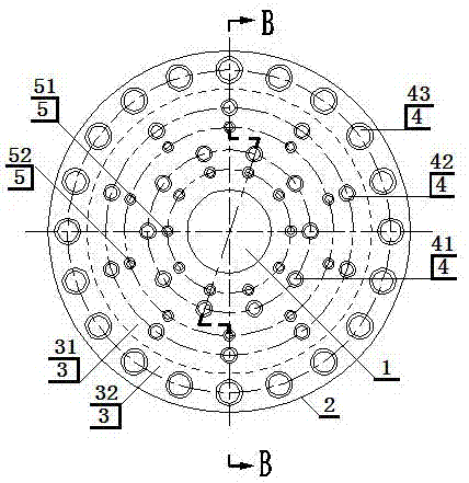
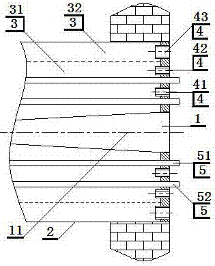
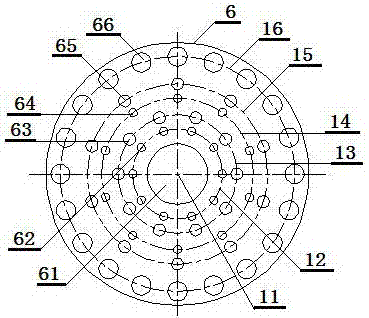
[0021] exist figure 1 , figure 2 and image 3Among them, the low NOx high calorific value gas burner of the present invention, the main body includes the inner throat 1, the outer throat 2, the combustion air passage 3, the air nozzle 4, the gas spray gun 5 and the front panel 6, which is characterized in that; The inner throat 1, the outer throat 2 and the combustion-supporting air channel 3 are arranged in a ring shape, with the center line of the inner throat 1 as the axis 11, and are arranged coaxially from the inside to the outside; the combustion-supporting air channel 3 is located at The annular cavity between the inner throat 1 and the outer throat 2 includes the main combustion air channel 31 on the side of the outer wall of the inner throat 1 and the auxiliary combustion air channel 32 on the side of the inner wall of the outer thro...


PUM


Abstract

The invention relates to a low-NOx and high-calorific value gas burner which comprises an inside throat inlet, an outside throat inlet, a main auxiliary combustion-supporting air channel, three stages of air supply functional components formed by an inside air nozzle, a middle air nozzle and an outside air nozzle, two stages of gas supply functional components formed by an inside gas spraying gun and an outside gas spraying gun and a front panel on which air supplying component mounting holes are reasonably distributed; forward spray orifices and lateral spray orifices are densely distributed on a head of a gas spraying gun; a mode that air and gas are uniformly distributed in pairs in two stages and in a misplacing manner respectively to supply gas to a main combustion region is adopted, so that uniform mixing of the gas and the air and rich combustion with ultra-low NOx generation quantity are facilitated; and by combining with a mode of supplying the gas toward the nearby of the cavity wall by adopting the third stage, a small part of gas which is not fully combusted in the main combustion region performs weak combustion which is beneficial to increasing the burnout degree of the gas in a region sufficient in combustion-supporting air, so that CO zero emission is realized, a high-calorific value gas boiler can be wholly ensured to reach a waste gas standard with low nitrogen and without CO emission, and basic guarantee is provided for application of high-calorific value gas to the gas boiler.

Description

technical field [0001] The invention relates to the technical field of gas boiler heating devices, in particular to a low NOx high calorific value gas burner. Background technique [0002] NOx is an important air pollutant and one of the culprits that cause acid rain and smog. With the strengthening of environmental protection and the deepening of energy-saving and emission-reduction policies in our country, the restrictions on NOx emissions from industrial gas-fired boilers are becoming increasingly strict. At present, the NOx emission concentration of natural gas low-nitrogen burners popular in the domestic and foreign markets is generally 100mg / Nm 3 Obviously, it cannot be applied to areas such as Beijing in my country where smog has always been serious. Since July 1, 2015, Beijing has introduced a 30mg / Nm NOx emission concentration for newly built gas-fired boilers. 3 the most stringent standards. For this reason, the industry has carried out a lot of exploration and...

Claims


Application Information

Patent Timeline
Patent Type & Authority Applications(China)
IPC IPC(8): F23D14/22F23D14/60
CPCF23D14/22F23D14/60F23C2201/30Y02E20/34
Inventor 陈宝明王秀学张鑫韦能权
Owner SHANGHAI WISEBOND TECH
Learn More