Wastewater treatment system and wastewater treatment method

A wastewater treatment system and technology of a treatment system, applied in the field of water treatment, can solve problems such as easy loss of microorganisms, poor water quality, and low recovery rate of produced water, so as to improve efficiency and operational stability, and avoid concentrated water disposal and treatment , The effect of improving the recovery rate of product water

Active Publication Date: 2017-12-29
北京众力清源环保科技有限公司
View PDF5 Cites 5 Cited by
  • Summary
  • Abstract
  • Description
  • Claims
  • Application Information

AI Technical Summary

Problems solved by technology

[0006] 1. For the anaerobic treatment technology adopted for organic matter, the easy loss of microorganisms leads to low anaerobic efficiency, and the high suspended matter in the effluent leads to high sludge concentration and large sludge volume in subsequent aerobic biochemical units;
[0007] 2. In the prior art, no targeted treatment measures have been taken for the higher hardness in the leachate, resulting in the use of external tubular ultrafiltration systems, nanofiltration systems and reverse osmosis systems, which are prone to fouling Blockage and complex maintenance and repair situations;
[0008] 3. The nitrification and denitrification aerobic MBR (membrane bioreactor, Membrane Bio-Reactor) treatment technology adopted for ammonia nitrogen in the A / O system is difficult to control the sludge activity in the nitrification process, and the denitrification effect in the denitrification process is poor. There are shortcomings such as large land occupation, high energy consumption, poor environment, and a large amount of biochemical sludge to be disposed of;
[0009] 4. The nanofiltration + reverse osmosis treatment technology adopted for salinity has a low recovery rate of produced water, poor quality of produced water, and difficult treatment and disposal of concentrated water

Method used


Image

  • Wastewater treatment system and wastewater treatment method
  • Wastewater treatment system and wastewater treatment method
  • Wastewater treatment system and wastewater treatment method

Examples


Embodiment Construction

[0048] In order to make the object, technical solution and advantages of the present invention clearer, the present invention will be described in further detail below in conjunction with specific embodiments and with reference to the accompanying drawings.

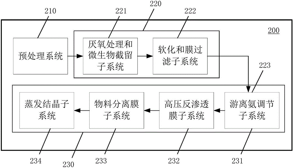
[0049] figure 2 is a schematic block diagram of a wastewater treatment system according to an embodiment of the present invention.

[0050] Such as figure 2 As shown, a wastewater treatment system 200 according to an embodiment of the present invention includes a pretreatment system 210 , a first treatment system 220 , and a second treatment system 230 .

[0051] The pretreatment system 210 performs conditioning treatment and precipitation treatment on the wastewater to obtain pretreated wastewater.

[0052] The first treatment system 220 performs anaerobic treatment and microbial interception on the pretreated wastewater, softens and membrane filters the wastewater intercepted by microorganisms, and obtains softened ...


PUM

PropertyMeasurementUnit
pressureaaaaaaaaaa

Abstract

The invention discloses a wastewater treatment system and a wastewater treatment method. The wastewater treatment system comprises a pretreatment system which is used for regulating and precipitating wastewater to obtain pretreated wastewater, a first treatment system which is used for performing anaerobic treatment and microbial retention on the pretreated wastewater and performing softening and membrane filtration on the microbial retained wastewater to obtain softened membrane-filtered effluent, and a second treatment system which is used for transforming free ammonia in the softened membrane-filtered effluent into ion ammonia to obtain transformed effluent and performing high-pressure reverse osmosis treatment, material separation treatment and evaporative crystallization treatment on the transformed effluent. According to the wastewater treatment system, specific pollutants can be relatively completely removed in each treatment unit on the technical process, and an advantageous treatment condition is created for the subsequent unit to form an innovative complete combination process, so that the treatment task of subsequent units becomes simpler, the treatment difficulty becomes lower, and the treatment effect becomes better.

Description

technical field [0001] The invention relates to the field of water treatment, in particular to a waste water treatment system and a waste water treatment method. Background technique [0002] In today's world, human beings are facing the problem of water shortage and increasingly serious water pollution. Therefore, water treatment technology, especially wastewater treatment technology, is becoming more and more important. [0003] In the current wastewater treatment technology, landfill leachate treatment technology is very important. The typical treatment technology of landfill leachate is "biological method (anaerobic + aerobic) + membrane method (ultrafiltration + nanofiltration + reverse osmosis)". This process can effectively remove pollutants in leachate, and has the technical Features such as maturity and simple process. [0004] figure 1 It is a flow chart of the current landfill leachate treatment method. Such as figure 1 As shown, the leachate first enters th...

Claims


Application Information

Patent Timeline
Patent Type & Authority Applications(China)
IPC IPC(8): C02F9/14
CPCC02F1/00C02F1/04C02F1/441C02F1/444C02F3/2846C02F5/02C02F5/06C02F9/00C02F2301/08
Inventor 沈东基岳东北李成海
Owner 北京众力清源环保科技有限公司
Why Eureka
Try Eureka