Three-section type carbon-based catalyst regeneration tower system

A carbon-based catalyst and regeneration tower technology, applied in the field of environmental engineering, can solve the problems of high operating cost of carbon-based catalyst regeneration tower, large load changes of power plant boilers, poor matching, poor flexibility, etc., to save energy consumption and increase residence time , The effect of improving regeneration efficiency

Pending Publication Date: 2018-01-05
GUODIAN SCI & TECH RES INST
View PDF3 Cites 12 Cited by
  • Summary
  • Abstract
  • Description
  • Claims
  • Application Information

AI Technical Summary

Problems solved by technology

[0007] Due to the problem of large load changes in power plant boilers, the flue gas volume varies greatly, resulting in poor compatibility and flexibility between the carbon-based catalyst regeneration tower with a single regeneration tower structure and the desulfurization and denitrification adsorption tower, and the operating cost of the carbon-based catalyst regeneration tower. high

Method used


Image

  • Three-section type carbon-based catalyst regeneration tower system

Examples


Embodiment 1

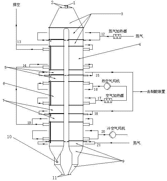
[0037] Such as figure 1 As shown, in the three-stage carbon-based catalyst regeneration tower system of the present invention, the regeneration tower body is divided into seven sections from top to bottom, which are respectively: preparation section 3, preheating section 4, first transition section 5, and heating section 6 , the second transition section 7, the cooling section 8 and the outlet section 9.

[0038] The three sections of preheating section 4, heating section 6 and cooling section 8 all adopt shell-and-tube heat exchange structure. The regeneration tower body is the tube side, the tube side uses carbon-based catalyst, and the shell side uses heat exchange medium. The carbon-based catalyst enters from the top of the tower, and reaches the bottom of the regeneration tower through the tube, wherein a first transition section 5 is set between the preheating section and the heating section, and a second transition section 7 is provided between the heating section and t...

Embodiment 2

[0043] In the three-stage carbon-based catalyst regeneration tower system of this example, the regeneration tower body is sequentially divided into a preparatory section, a preheating section, a first transition section, a heating section, a second transition section, a cooling section and an outlet section from top to bottom. The heat exchange medium in the shell side of the preheating section adopts electric heating or other heat sources, and the structure of other parts is the same as that of the first embodiment. This system may cause energy waste. On the one hand, the heat absorbed by the cooling section is not fully utilized, and on the other hand, an additional heat source is added to the preheating section.

Embodiment 3

[0045] In the three-stage carbon-based catalyst regeneration tower system of this example, the regeneration tower body is sequentially divided into a preparatory section, a preheating section, a first transition section, a heating section, a second transition section, a cooling section and an outlet section from top to bottom. Wherein the preparatory section is not provided with a nitrogen heater, and other parts of the structure are the same as in Embodiment 1. In this system, nitrogen is used as a protective gas and directly passed into the preparation section of the regeneration tower through the pipeline. In this way, the temperature of the SO2-enriched gas in the transition section cannot be increased, and the pipeline corrosion and equipment failure rate will be high.


PUM


Abstract

The invention provides a three-section type carbon-based catalyst regeneration tower system which can improve an energy utilization rate in a carbon-based catalyst regeneration process and enhance matching and flexibility between a carbon-base catalyst regeneration tower and a desulfurization and denitrification adsorption tower. A tower body of the three-section type carbon-based catalyst regeneration tower system disclosed by the invention is sequentially divided into a preparing section, a preheating section, a first transition section, a heating section, a second transition section, a cooling section and an outlet section from top to bottom; the three sections of the preheating section, the heating section and the cooling section are all of tube-shell type heat exchange structures; thetower body of the regeneration tower serves as a tube pass, a carbon-based catalyst passes through the tube pass, and a heat exchange medium passes through a shell pass; the carbon-based catalyst enters to the tower top and reaches the bottom of the regeneration tower through the tube pass; the first transition section is arranged between the preheating section and the heating section, the secondtransition section is arranged between the heating section and the cooling section, the two transition sections are used for exhausting enrichment SO2 gas in the tower, and the exhausted SO2 gas is introduced into an acid making device.

Description

technical field [0001] The invention belongs to the field of environmental engineering, and in particular relates to a three-stage carbon-based catalyst regeneration tower in a combined boiler flue gas desulfurization and denitrification device using a carbon-based catalyst as an adsorbent and a catalyst. Background technique [0002] Carbon-based catalyst dry flue gas pollutant control technology can realize the integration of desulfurization and denitrification, and can also remove smoke, SO 3 , heavy metals and other impurities. This technology basically does not consume water and saves a lot of water resources. The desulfurization efficiency is high. The by-product of desulfurization is high concentration SO. 2 , to facilitate resource utilization, this is a new generation of flue gas pollutant control technology with obvious advantages. It has great application prospects in many fields such as iron and steel, metallurgy, electric power, and waste incineration. [000...

Claims


Application Information

Patent Timeline
Patent Type & Authority Applications(China)
IPC IPC(8): B01J38/02B01J38/04
Inventor 邢德山程文煜张乾柴晓琴蔡彦吟延寒胡宇峰谷建功
Owner GUODIAN SCI & TECH RES INST
Why Eureka
Try Eureka