A kind of flue gas denitrification, desulfurization and dust removal process method

A process method, desulfurization and dust removal technology, applied in the field of flue gas denitrification, desulfurization and dust removal, which can solve the problems of pollution, corrosion, and equipment corrosion in the plant area and its surrounding environment, so as to avoid corrosion of chimneys, avoid fouling and blockage, and eliminate white smoke exhaust. Effect

Active Publication Date: 2020-09-11
SHENYANG INSTITUTE OF CHEMICAL TECHNOLOGY +1
View PDF10 Cites 0 Cited by
  • Summary
  • Abstract
  • Description
  • Claims
  • Application Information

AI Technical Summary

Problems solved by technology

However, because the untreated flue gas cannot dissipate quickly, especially when the temperature and air pressure in the local area are low or during the period of cloudy weather, the dust and liquid droplets carried in the flue gas gather near the chimney and fall to the ground to form "gypsum rain". ” or acid rain, polluting the factory area and the surrounding environment, and even corroding equipment
At present, many power plants install gas-gas heat exchangers (GGH) to increase the exhaust gas temperature and eliminate white fog in the chimney, but the problems of GGH blockage, corrosion and air leakage are difficult to solve

Method used


Image

  • A kind of flue gas denitrification, desulfurization and dust removal process method
  • A kind of flue gas denitrification, desulfurization and dust removal process method

Examples


Embodiment 1

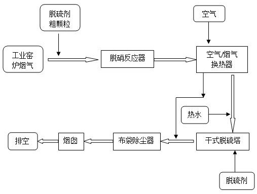
[0030] like figure 1 As shown, the flue gas from the industrial kiln is introduced into the coarse particle desulfurizer before entering the denitrification reactor, and the NOx in the flue gas reacts with ammonia under the action of the catalyst in the denitrification reactor to form nitrogen and water. The flue gas after denitrification enters the air / flue gas heat exchanger to cool down, then goes through hot water (water bath or spraying superheated water) to adjust the humidity, and then enters the dry desulfurization tower. The desulfurizer is supplied into the desulfurization tower in the form of dry powder, and the SO in the flue gas 2 The reaction produces dry powdered desulfurization ash. The flue gas containing desulfurization ash and dust exported from the dry desulfurization tower is mixed with the hot air from the air / flue gas and then enters the bag filter for dust removal. The clean flue gas after dust removal is emptied through the chimney.

Embodiment 2

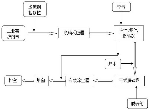
[0032] like figure 2 As shown, the flue gas from an industrial kiln is introduced into a coarse desulfurizer before entering the denitrification reactor, and the NOx in the flue gas reacts with ammonia under the action of a catalyst in the denitrification reactor to form nitrogen and water. The flue gas after denitrification enters the air / flue gas heat exchanger to cool down, then goes through hot water (water bath or spraying superheated water) to adjust the humidity, and then enters the dry desulfurization tower. The desulfurizer is supplied into the desulfurization tower in the form of dry powder, and the SO in the flue gas 2 The reaction produces dry powdered desulfurization ash. The flue gas containing desulfurization dust from the dry desulfurization tower enters the bag filter for dust removal. The clean flue gas after dust removal is mixed with the hot air from the air / flue gas and then emptied through the chimney.


PUM


Abstract

A flue gas denitrification, desulfurization, and dust removal process method relates to a flue gas treatment process. The present invention introduces a coarse particle desulfurizer into the flue gas from a combustion device, and enters a denitrification reactor after pre-desulfurization; the flue gas after denitrification Entering air / flue gas heat exchange and cooling. The cooled flue gas enters the dry desulfurization tower after humidity adjustment, and the dry desulfurization tower uses dry powder desulfurization agent; after desulfurization, the flue gas containing dust such as post-reaction desulfurization agent enters the bag filter for dust removal, and comes from the air / flue gas exchange The hot air from the heater is mixed with the flue gas before or after the dust collector, and the purified flue gas mixed with the hot air is introduced into the chimney for discharge. The process of the invention avoids fine dust from clogging the pores of the denitrification catalyst and its deactivation. The dry desulfurization agent can be directly used for dry desulfurization through flue gas humidity control. The mixing of hot air and flue gas prevents chimney corrosion and white mist exhaust. form.

Description

technical field [0001] The invention relates to a method for treating industrial flue gas, in particular to a flue gas denitrification, desulfurization, and dust removal process. Background technique [0002] The main pollutants in the flue gas produced by fossil fuel combustion are SO 2 , NOx and dust. In recent years, with the strict requirements of environmental protection standards, the pollution control of industrial furnace flue gas in all walks of life has become increasingly urgent. Due to different fuel sources and combustion conditions, industrial furnaces produce different flue gas components, such as tunnel kilns in the refractory industry, glass kilns, chemical industrial furnaces, and heating furnaces in the metallurgical industry. Low (such as <300 ℃), some contain very fine dust. If the traditional denitration process is adopted, the denitration efficiency is low, and it is easy to cause deactivation of the denitration catalyst. [0003] For most indust...

Claims


Application Information

Patent Timeline
Patent Type & Authority Patents(China)
IPC IPC(8): B01D53/75B01D53/90B01D53/56B01D53/83B01D53/50B01D46/02
Inventor 许光文程继光韩振南石磊朱庆凯
Owner SHENYANG INSTITUTE OF CHEMICAL TECHNOLOGY
Why Eureka
Try Eureka