Ion optical excitation afterproduct researching method

A post-product, light-excited technology, applied in the direction of ion sources/guns, parts of particle separator tubes, particle separation tubes, etc., can solve problems such as inability to detect delayed emission electrons, and achieve high ion density

Active Publication Date: 2018-01-09
天津来津文化科技有限公司
View PDF4 Cites 2 Cited by
  • Summary
  • Abstract
  • Description
  • Claims
  • Application Information

AI Technical Summary

Problems solved by technology

[0003] In some polyatomic anion systems, according to the non-adiabatic coupling, the electron energy obtained by photoexcitation is distributed according to its vibration degree of freedom; when the vibration energy is reconverted into electron energy, the electron is emitted from the system. This process is relatively The process of photoexcitation has a delay on the order of micros

Method used


Image

  • Ion optical excitation afterproduct researching method

Examples


Embodiment Construction

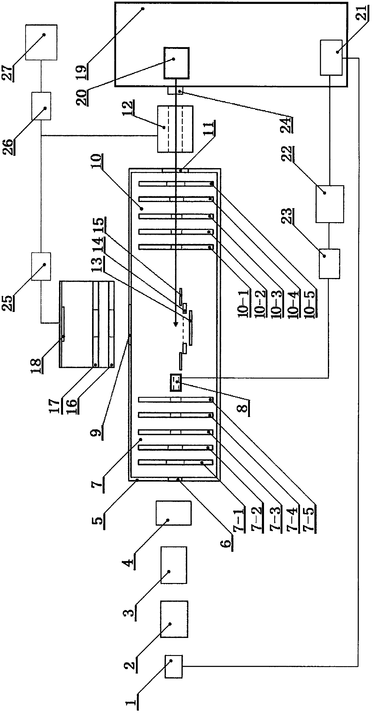
[0027] Such as figure 1 It is a structural schematic diagram of the present invention, and the device mainly includes an ion source (1), an accelerator (2), a time-of-flight mass spectrometer (3), a particle mass selector (4), a magnetic shield (5), an ion beam entrance (6), and Focusing electrode group (7) composed of electrode I (7-1), electrode II (7-2), electrode III (7-3), electrode IV (7-4), electrode V (7-5), and cluster electrodes (8), photoelectron exit (9), composed of electrode VI (10-1), electrode VII (10-2), electrode VIII (10-3), electrode IX (10-4), electrode X (10-5) Composed of mass selective electrode group (10), ion outlet (11), ion detector (12), electron background reduction plate (13), reflector plate (14), ion correction plate (15), extraction electrode (16), Focusing electrodes (17), electron detectors (18), lasers (19), regenerative amplifiers (20), fiber optic oscillators (21), FPGAs (22), signal generators (23), optical signal delay units (24 ), an...


PUM


Abstract

The invention relates to the field of optoelectronics and molecular reaction dynamics, and a method for researching products after ion photoexcitation. After ions are accelerated through time-of-flight mass spectrometry and particle mass selectors, they enter a magnetic shield; ion fragments and laser pulses are synchronized to generate ion fragment; set the voltage of the focusing electrode group to zero, and apply a voltage to the mass-selective electrode group, so that the voltage on the electrode increases according to the same slope; after the ion beam fragment passes through the focusing electrode group, a pulsed electric field is applied to the focusing electrode group; After the ions leave the mass selective electrode set, the voltage on the mass selective electrode set is set to zero, and the ions interact with the laser to generate ion fragments and photoelectrons; the ion fragments fly to the focusing electrode set and are reflected, and fly to the ion detection through the mass selective electrode set The photoelectrons generated by the interaction between the ion beam and the laser are emitted, and are accelerated by the extraction electrode and the focusing electrode to reach the electron detector; compare the ion fragments and the photoelectron information.

Description

technical field [0001] The invention relates to the field of optoelectronic imaging technology and molecular reaction dynamics, in particular to a method for researching products after ion photoexcitation, which can simultaneously perform imaging of electrons and ion fragments, and has the ability to detect instantaneously emitted electrons and delayed emitted electrons. method. Background technique [0002] Particle velocity imaging technology is an important method for the study of molecular reaction dynamics. Its most important feature is that it can obtain the full three-dimensional velocity and direction distribution of scattering particles in one image at the same time, that is, it can simultaneously obtain the energy spectrum of particles. information and angular distribution information. Particle velocity imaging techniques can be applied in simultaneous measurements of photodissociation, where photodissociation of electrons in steady-state molecular anions produces...

Claims


Application Information

Patent Timeline
IPC IPC(8): H01J49/10H01J49/00H01J49/40
Inventor 李君华张向平赵永建
Owner 天津来津文化科技有限公司
Why Eureka
Try Eureka