Heat engine-hydrogen reaction bed combined cycle system
A circulation system and reaction bed technology, applied in mechanical equipment, steam engine devices, machines/engines, etc., can solve the problem of low utilization rate of hydrogen energy
- Summary
- Abstract
- Description
- Claims
- Application Information
AI Technical Summary
Problems solved by technology
Method used
Image
Examples
Embodiment 1
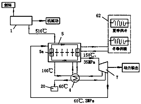
[0040] Heat engine-hydrogen reaction bed combined cycle system of the present invention such as figure 1 As shown, it includes a heat engine 1, a hydrogen compression unit 5, a building energy supply system 62, an intermediate reheater 4 and an expander 7, and the heat engine is a gas turbine. The hydrogen compression unit includes 6 hydrogen reaction beds. The 6 hydrogen reaction beds are equipped with internal heat exchange pipelines to perform hydrogen desorption and hydrogen absorption alternately. The 6 hydrogen reaction beds are connected to the building energy supply system. Such as Figure 5 As shown, the intermediate reheater is a shell-and-tube heat exchanger, which is respectively provided with a heat exchange tube 15, a hydrogen inlet 13, a hydrogen outlet 16, a flue gas inlet 17, and a flue gas outlet 14, the flue gas goes through the shell side, and the hydrogen gas goes through the pipe Procedure. Such as Figure 6 As shown, the expander is a three-stage expa...
Embodiment 2
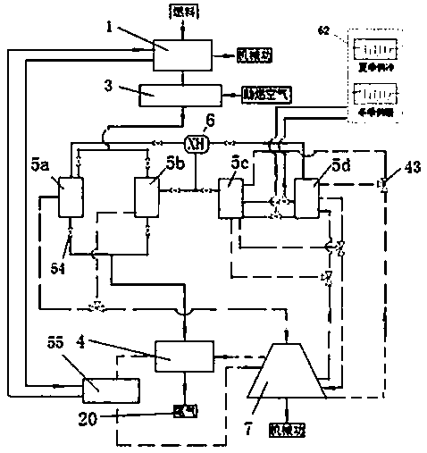
[0053] Another embodiment of the present invention is as figure 2 As shown, it includes a heat engine 1 , a hydrogen compression unit, a combustion chamber 3 , an intermediate reheater 4 , a cylinder cooler 55 , an expander 7 and a first metal hydride replacement device 6 . The heat engine is a piston engine, and the cylinder cooler is connected to the heat engine cycle, and the heat from the cooling cylinder heats the circulating hydrogen drawn from the expander. The hydrogen compression unit is equipped with two sets of hydrogen reaction beds, each with two hydrogen reaction beds, namely No. 1 hydrogen reaction bed 5a, No. 2 hydrogen reaction bed 5b, No. 3 hydrogen reaction bed 5c and No. 4 hydrogen reaction bed 5d. The hydrogen reaction beds are arranged side by side. The flue gas inlet and outlet of No. 1 hydrogen reaction bed 5 a and No. 2 hydrogen reaction bed 5 b are provided with valves 54 . The two hydrogen reaction beds in each group alternately perform hydrogen a...
Embodiment 3
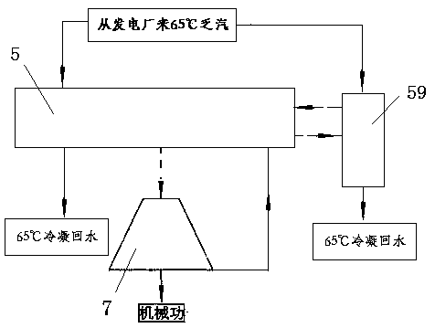
[0058] Another embodiment of the present invention is as image 3 As shown, it includes a hydrogen compression unit 5, an expander 7, an absorption refrigeration device 59, a 65°C exhaust steam pipeline from a power plant and a 65°C condensation return water pipeline. The 65°C exhaust steam pipeline from the power plant is connected to the 65°C condensate return water line through the hydrogen compression unit and absorption refrigeration equipment to return to the power plant. The hydrogen outlet of the hydrogen compression unit is connected to the inlet of the expander, and the outlet of the expander is connected to the hydrogen compression unit. The hydrogen reaction bed of the hydrogen compression unit performs hydrogen desorption and hydrogen absorption alternately, and the hydrogen compression unit is connected to the absorption refrigeration equipment 59 in a cycle. Such as Figure 8 As shown, the hydrogen reaction bed is a casing structure, including a hydrogen circu...
PUM
 Abstract
Description
Claims
Application Information
 - R&D
- Intellectual Property
- Life Sciences
- Materials
- Tech Scout
- Unparalleled Data Quality
- Higher Quality Content
- 60% Fewer Hallucinations
Browse by: Latest US Patents, China's latest patents, Technical Efficacy Thesaurus, Application Domain, Technology Topic, Popular Technical Reports.
© 2025 PatSnap. All rights reserved.Legal|Privacy policy|Modern Slavery Act Transparency Statement|Sitemap|About US| Contact US: help@patsnap.com


