Ultra-thin metal grid-based transparent electrode and preparation method thereof

A transparent electrode, ultra-thin metal technology, applied in cable/conductor manufacturing, conductive layer on insulating carrier, nanotechnology for materials and surface science, etc., can solve the problem of reducing the surface energy difference of metal and substrate, metal surface Poor wettability, weak light transmittance, etc., to achieve the effect of low vacuum, low cost, and less material

Active Publication Date: 2018-01-19
NINGBO INST OF MATERIALS TECH & ENG CHINESE ACADEMY OF SCI +1
View PDF8 Cites 4 Cited by
  • Summary
  • Abstract
  • Description
  • Claims
  • Application Information

AI Technical Summary

Problems solved by technology

In this application, firstly, the thickness of the metal grid is relatively thick, so its light transmittance is weak, and secondly, the application does not reduce the surface energy difference between the metal and the substrate, and the wettability of the metal surface is poor
CN 102593194 A discloses a transparent electrode substrate and its manufacturing method as well as electronic equipment and solar cells with the transparent electrode substrate. The application forms a first transparent conductive layer on one side of the transparent substrate; forms a conductive layer on the first transparent conductive layer. Metal layer; conduct photoresist patterning on the conductive metal layer to form a conductive metal mesh layer; form a second transparent conductive layer on the surface of the conductive metal mesh layer, the application has a complex structure

Method used


Image

  • Ultra-thin metal grid-based transparent electrode and preparation method thereof
  • Ultra-thin metal grid-based transparent electrode and preparation method thereof
  • Ultra-thin metal grid-based transparent electrode and preparation method thereof

Examples


Embodiment 1

[0037] A transparent electrode based on an ultra-thin metal grid, the transparent electrode generally includes a flexible transparent substrate, and an Ag grid layer with a thickness of 9 nm is deposited on one side of the flexible transparent substrate.

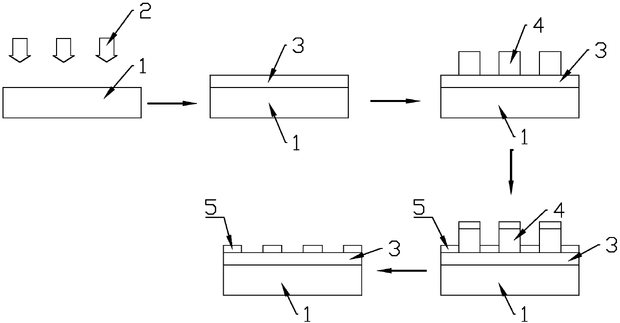
[0038] The ultra-thin metal grid transparent electrode is prepared by the following method:

[0039] (1) UV treatment is carried out to the flexible transparent substrate;

[0040] (2) Use polyetherimide (PEI) to graft a layer of amine groups on the surface of the flexible transparent substrate;

[0041] (3) Forming a mask with a period of 1400 nm on the surface of the substrate by colloid printing;

[0042] (4) Using the method of electron beam evaporation, metal Ag is deposited on the mask plate, and the initial pressure is 6×10 4 Pa, the evaporation rate is 1.7 angstroms / s, the power is 9kw, the coating stops after 9s, and a 9nm silver grid film is grown on the substrate surface at the gap of the mask;

[0043] (5) Tak...

Embodiment 2

[0052] A transparent electrode based on an ultra-thin metal grid, the transparent electrode generally includes a flexible transparent substrate, and an Au grid layer with a thickness of 9 nm is deposited on one side of the flexible transparent substrate.

[0053] The transparent electrode of the ultra-thin metal grid is prepared by the following method:

[0054] (1) UV treatment is carried out to the flexible transparent substrate;

[0055] (2) Use polyetherimide (PEI) to graft a layer of amine groups on the surface of the flexible transparent substrate;

[0056] (3) Form a mask plate with a period of 100 μm on the surface of the substrate by photolithography technology;

[0057] (4) Using the method of electron beam evaporation, metal Au is deposited on the mask plate, and the initial pressure is 6×10 4 Pa, the power is 9kw, the evaporation rate is 6 angstroms / s, the coating stops after 9s, and a 9nm Au grid film is grown on the substrate surface at the gap of the mask;

[0...

Embodiment 3

[0061] A transparent electrode based on an ultra-thin metal grid. The transparent electrode includes a flexible transparent substrate, and a double-period Ag and Au grid layer is deposited on one side of the flexible transparent substrate.

[0062] The transparent electrode of the ultra-thin metal grid is prepared by the following method:

[0063] (1) UV treatment is carried out to the flexible transparent substrate;

[0064] (2) Use polyetherimide (PEI) to graft a layer of amine groups on the surface of the flexible transparent substrate;

[0065] (3) Forming a mask with a period of 1400 nm on the surface of the substrate by colloid printing;

[0066] (4) Using the method of electron beam evaporation, metal Ag is deposited on the mask plate, and the initial pressure is 6×10 4 Pa, the power is 9kw, the evaporation rate is 1.7 angstroms / s, the coating stops after 9s, and a 6nm Ag grid film is grown on the substrate surface at the gap of the mask;

[0067] (5) Take out the co...


PUM

PropertyMeasurementUnit
Thicknessaaaaaaaaaa
Thicknessaaaaaaaaaa
Square resistanceaaaaaaaaaa

Abstract

The invention discloses an ultra-thin metal grid-based transparent electrode and a preparation method thereof, and relates to the technical field of a transparent electrode. The ultra-thin metal grid-based transparent electrode comprises a surface modified flexible transparent substrate; and a conductive metal grid layer with thickness of 1-10nm is deposited on the modified surface of the flexibletransparent substrate. The preparation method of the transparent electrode comprises the steps of grafting a layer of amino group on the surface of the substrate, forming a mask plate by photoresistor adhesive printing, depositing a metal layer with thickness of 1-10nm in the gap of the mask plate, and removing the mask plate to obtain the ultra-thin metal grid-based transparent electrode. By lowering the thickness of the metal grids, the light transmittance of the metal grids is improved; and meanwhile, the metal grids still have relatively high conductivity at the thickness of 1-10nm, so that the problem of "waxing and waning" between the conductivity and the light transmittance of the transparent electrode can be solved, and balance of the conductivity and the light transmittance is realized.

Description

technical field [0001] The invention relates to the technical field of transparent electrodes, in particular to a transparent electrode based on an ultra-thin metal grid and a preparation method thereof Background technique [0002] Transparent electrodes are widely used in various optoelectronic functional materials and devices, including solar cells, photodetection and sensors, image sensors, displays, organic light-emitting diodes and touch screen panels, due to their high optical transmittance and low resistivity. At present, transparent electrodes mainly include: indium tin oxide (ITO) transparent electrodes, carbon nanotube transparent electrodes, graphene transparent electrodes, metal nanowire transparent electrodes, metal grid transparent electrodes, etc. [0003] Conductivity and light transmittance are the main performance indicators of transparent electrode materials. Most transparent electrode materials need to balance the performance of the two, but many transpa...

Claims


Application Information

Patent Timeline
IPC IPC(8): H01B5/14H01B13/00B82Y30/00B82Y40/00
Inventor 叶继春杨熹高平奇邬苏东肖剑峰黄志林夏金才周建宏
Owner NINGBO INST OF MATERIALS TECH & ENG CHINESE ACADEMY OF SCI
Why Eureka
Try Eureka