
Intensive oily sludge processing prying tool

An intensive, oily sludge technology, applied in sludge treatment, water/sludge/sewage treatment, dehydration/drying/thickened sludge treatment, etc., can solve the problem of harming personal and environmental safety, high treatment cost and complex process and other problems, to achieve the effect of improving separation efficiency and recovery efficiency, high separation efficiency and good separation effect

Active Publication Date: 2018-01-30
HEILONGJIANG LANDE ULTRASONIC TECH CO LTD
View PDF5 Cites 4 Cited by
  • Summary
  • Abstract
  • Description
  • Claims
  • Application Information

AI Technical Summary

Problems solved by technology

But wherein many methods all have some problems, are very unsuitable for practical application, as: incineration method consumes a lot of energy, easily produces secondary pollution, and oil resource has not been recycled; The biodegradation of petroleum hydrocarbons, the same oil resources have not been recycled; the problems of the solvent extraction method are long process, complicated process, high treatment cost, and it is only suitable for oily sludge containing a large amount of refractory organic matter; solid-liquid separation method is for Low oil recovery rate of oily sludge with high oil content and serious pollution
[0006] 1. Chemical agents need to be added in the process of sludge treatment, and the treatment cost is high; if the agents are not properly managed in the process of use, storage, and transportation, it is easy to cause secondary pollution, and even endanger personal and environmental safety;
[0007] 2. Some treatment methods need to incinerate the remaining residues, and burn the remaining oil in the residues, which is a great waste of resources; and the waste gas generated after combustion has a large content of nitrogen and sulfur, which is easy to cause secondary pollution to the air;
[0008] 3. Part of the treatment method adopts the method of reinjection to inject the sludge back into the water injection well, which may affect the life of the water injection well; at the same time, the oil contained in the sludge cannot be used, which is a waste of resources;
[0009] 4. The existing treatment methods have low efficiency and small treatment capacity, and the amount of sludge accumulated in major oil fields in my country is too large to be treated in time, causing continuous pollution to the environment; some treatment methods need to heat the sludge to a higher temperature , high energy consumption and high cost

Method used


Image

  • Intensive oily sludge processing prying tool
  • Intensive oily sludge processing prying tool
  • Intensive oily sludge processing prying tool

Examples


specific Embodiment approach 1

[0053] Such as Figure 1-11 As shown, an intensive oil sludge treatment skid includes a pre-sludge pretreatment device 1, a post-sludge pretreatment device 2, an intensive treatment device 3 and an oil-cement separation device 4, and the pre-sludge pretreatment device 1 is connected to the post-sludge pretreatment device 2; the post-sludge pretreatment device 2 is connected to the intensive treatment device 3; the intensive treatment device 3 is connected to the oil-cement separation device 4.

specific Embodiment approach 2

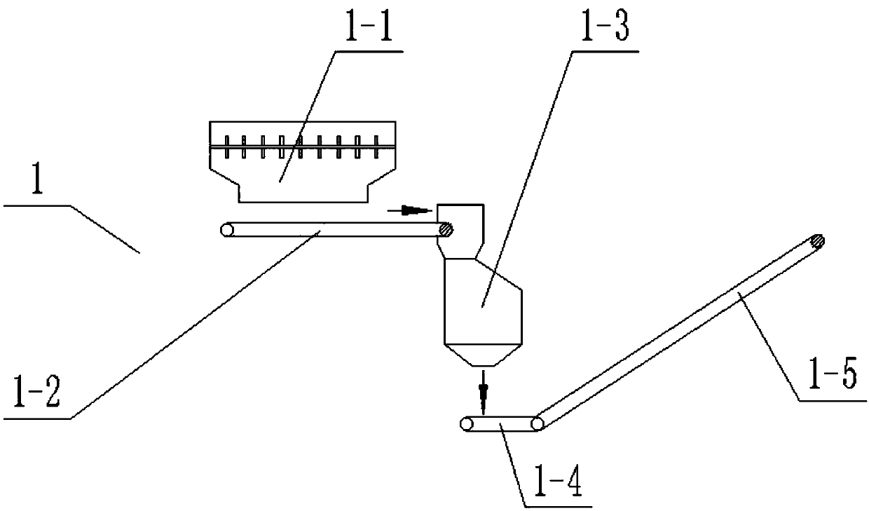
[0054] The pre-sludge pretreatment device 1 includes a shearing machine 1-1, a belt conveyor I1-2, an upper and lower double-roll crusher 1-3, a belt conveyor II1-4 and a belt conveyor III1-5, and the shears The cutting machine 1-1 is arranged on the upper end of the belt conveyor I1-2, and the discharge port of the shearing machine 1-1 is set up against the belt on the belt conveyor I1-2; the right end of the belt conveyor I1-2 is inserted into To the upper end of the upper and lower double-roll crusher 1-3; the upper and lower double-roll crusher 1-3 is arranged on the upper end of the belt conveyor II1-4, and the discharge port of the upper and lower double-roll crusher 1-3 is directly opposite to the belt conveyor The belt conveyor II1-4 is set; the right end of the belt conveyor II1-4 is connected to the belt conveyor III1-5; the belt conveyor I1-2 and the belt conveyor II1-4 are horizontally arranged belt conveyors; The belt conveyor III1-5 is an inclined belt conveyor; ...

specific Embodiment approach 3

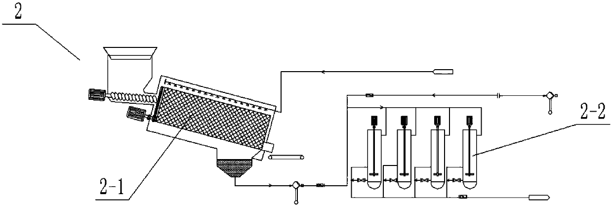
[0055] Such as Figure 1-11As shown, the post-sludge pretreatment device 2 includes a pre-treatment device 2-1 and a post-treatment device 2-2, and the pre-treatment device 2-1 includes a solid sludge sludge feed hopper 2-1-1, a screw pusher Inclined hopper 2-1-2, screw pushing device 2-1-3, screening box 2-1-4, drum type screening machine 2-1-5, spray pipe assembly 2-1-6, mixing water tank 2 -1-7, coarse material conveyor 2-1-8, flushing water inlet pipe 2-1-9 and slurry conveying pipe 2-1-10; the solid sludge feed hopper 2-1-1 is connected and set At the rear end of the front sludge pretreatment device 1; the solid sludge feed hopper 2-1-1 is arranged at the upper end of the inner side of the spiral push slant hopper 2-1-2; the spiral push slant hopper 2- The lower end of 1-2 is connected to the left side of the screening box 2-1-4; the inner lower end of the spiral pushing inclined hopper 2-1-2 is provided with a screw pushing device 2-1-3; the screening The inner middle ...


PUM


Abstract

The invention relates to the field of oily sludge processing, in particular to an intensive oily sludge processing prying tool. The intensive oily sludge processing prying tool comprises a front oilysludge preprocessing device, a rear oily sludge preprocessing device, an intensive processing device and an oily sludge and water sludge separation device, wherein the front oily sludge preprocessingdevice and the rear oily sludge preprocessing device are connected; the rear oily sludge preprocessing device is connected with the intensive processing device; the intensive processing device is connected with the oily sludge and water sludge separation device. According to the intensive oily sludge processing prying tool, various physical effects and functions are used for processing the oily sludge, no chemical agents need to be added to realize the processing of the oily sludge, and no secondary environment pollution is generated. The intensive oily sludge processing prying tool has the advantages of large equipment handling capacity, high efficiency, good effect and low cost. Since a prying structure is adopted, land occupation is small. During a short-time operation, the intensive oily sludge processing prying tool is put on the right side of a platform trailer to be used, and is put on the ground to be fixedly used during a long-time operation so as to be agile and mobile.

Description

technical field [0001] The invention relates to the field of sludge treatment, in particular to an intensive oil sludge treatment skid. Background technique [0002] Sludge is the main pollutant produced in the process of petroleum development, production and processing. According to different causes, it is mainly divided into landing sludge, tank bottom sludge, ground oil spill, oil refinery sludge, etc. [0003] The composition of oil sludge is extremely complex, and varies with geological conditions and production processes. It is generally composed of water, soil, and oily organic matter. Sludge sludge mainly has the following characteristics: high water content and large volume; complex composition and difficult treatment; it contains a large amount of dirty oil and combustible substances; most of the harmful components exceed the emission standards. At present, although there are many oily sludge pollution control technologies at home and abroad, there is no targeted...

Claims


Application Information

Patent Timeline
IPC IPC(8): C02F11/00C02F11/12B01J19/18B01J19/10
CPCY02W10/40
Inventor 赵宪忠张修全高曼琦张健任建军
Owner HEILONGJIANG LANDE ULTRASONIC TECH CO LTD
Learn More