Preparation of spinel catalyst and application thereof to elimination of nitrogen oxides

A technology of nitrogen oxides and catalysts, applied in the field of preparation of high-efficiency denitrification catalysts at low temperatures, can solve the problems of 1D nanomaterials that have not been reported, and achieve the effects of wide industrial application prospects, high resistance to SO2 poisoning, and reduced synthesis costs

Inactive Publication Date: 2018-03-13
FUJIAN INST OF RES ON THE STRUCTURE OF MATTER CHINESE ACAD OF SCI
View PDF0 Cites 14 Cited by
  • Summary
  • Abstract
  • Description
  • Claims
  • Application Information

AI Technical Summary

Problems solved by technology

Compared with traditional nanomaterials, these nanomaterials have more excellent electrochemical and sensing properties, but it has not been reported to use this method to prepare various 1D nanomaterials and apply them to NO. x Elimination reaction

Method used


Image

  • Preparation of spinel catalyst and application thereof to elimination of nitrogen oxides
  • Preparation of spinel catalyst and application thereof to elimination of nitrogen oxides
  • Preparation of spinel catalyst and application thereof to elimination of nitrogen oxides

Examples


Embodiment 1

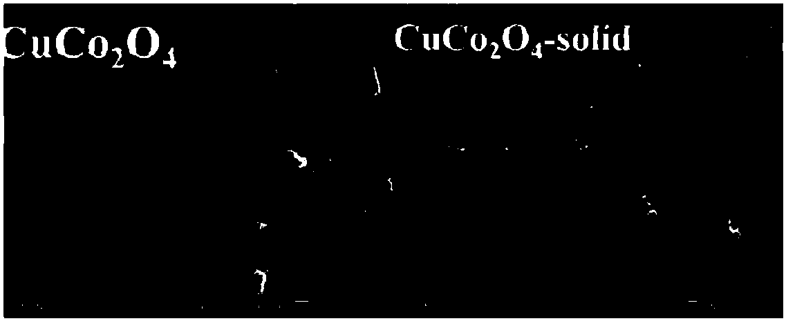
[0027] The present invention will be 0.4mmol Cu(NO 3 ) 2 ·3H 2 O and 0.8mmolCo(NO 3 ) 2 ·6H 2 O was dissolved in 19mL DMF, then 1.44mmolCA and 1.2g PAN were added to the above solution, and stirred at room temperature for 24h. The uniformly stirred solution was passed through an electrospinning device to form one-dimensional nanofibers under the conditions of 22kV and 1mL / h. The collected nanofibers were dried at 100 °C and calcined at 400 °C. The heating rate during the roasting process was 0.5 °C / min. The prepared catalyst was marked as CuCo 2 o 4 .

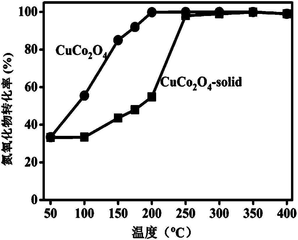
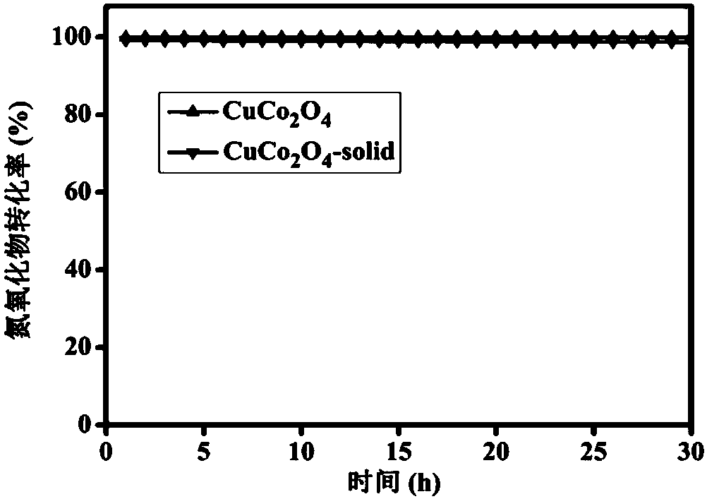
[0028] NO x Elimination process: take 0.5ml sample and place it in a u-shaped (i.d=8mm) quartz tube, and carry out NO x Determination of reduction performance, space velocity 150,000h -1 , sample, constant temperature reduction of NO at 50-400°C x , gas volume composition is 294ppm NO, 350ppm NH 3 , 3vol%O 2 (Ar balance gas), NO x Conversion by chemiluminescence NO-NO 2 -NO x Analyzer detection (Thermo, 42i-HL)....

Embodiment 2

[0030] The present invention will be 0.4mmol Cu(NO 3 ) 2 ·3H 2 O and 0.8mmol Co(NO 3 ) 2 ·6H 2 O was dissolved in 19mL DMF, then 1.44mmol CA and 1.2g PAN were added to the above solution, and stirred at room temperature for 24h. The uniformly stirred solution was passed through an electrospinning device to form one-dimensional nanofibers under the conditions of 22kV and 1mL / h. The collected nanofibers were dried at 100°C and calcined at 400°C. During the calcining process, the heating rate was 10°C / min. The prepared catalyst was marked as CuCo 2 o 4 -solid (such as figure 1 shown). NO x Elimination process: take 0.5ml sample and place it in a u-shaped (i.d=8mm) quartz tube, and carry out NO x Determination of reduction performance, space velocity 150,000h -1 , sample, constant temperature reduction of NO at 50-400°C x , gas volume composition is 294ppm NO, 350ppm NH 3 , 3vol%O 2 (Ar balance gas), NO x Conversion by chemiluminescence NO-NO 2 -NO x Analyzer dete...


PUM

PropertyMeasurementUnit
specific surface areaaaaaaaaaaa

Abstract

The present invention provides a highly active spinel-type catalyst for elimination of nitrogen oxides from coal-fired flue gas emissions from thermal power plants and nitric acid plants. The catalystexhibits a high NOx conversion rate in a wide air-fuel ratio range and exhibits excellent low-temperature activity. The prepared catalyst is prepared by a high-voltage electrospinning method. The spinel components mainly include CuCo2O4, NiCo2O4, FeCo2O4, CoMn2O4, CoFe2O4, etc. The morphology of the prepared catalyst, such as crystal faces and size, can be controlled by combination of the electrospinning method and a heat treatment process. The performance of hollow tubular spinel in NOx elimination is much better than that of solid nanorods. The denitration effect of the catalyst provided bythe present invention is superior to that of a conventional NOx elimination catalyst. The preparation method is simple, the operation is convenient, the cost is low, the NOx conversion rate is high,and obvious industrial application value is provided.

Description

technical field [0001] The invention belongs to the field of nano-catalysis application, and in particular relates to a preparation method of a high-efficiency denitration catalyst at low temperature. Background technique [0002] In recent years, the problem of environmental pollution has attracted more and more attention and attention from all over the world. Especially in China, the smog problem has become a major social issue related to the sustainable development of the national economy and the health of people's lives. Nitrogen oxides (NO x ) is one of the main precursors to produce photochemical smog, while diesel vehicle exhaust, coal-fired power plant exhaust gas and coal-fired industrial boiler flue gas are the main sources of NO x main source of . After years of development in our country, various NO x Although the removal technology has been widely used, but due to the NO x The general situation of pollution leading to smog has not been fundamentally curbed....

Claims


Application Information

Patent Timeline
Patent Type & Authority Applications(China)
IPC IPC(8): B01J21/10B01J23/34B01J23/72B01J23/745B01J23/75B01J23/755B01J23/889B01D53/86B01D53/56
CPCB01J23/75B01D53/8628B01D2258/02B01D2258/0283B01J21/005B01J21/10B01J23/005B01J23/34B01J23/72B01J23/745B01J23/755B01J23/78B01J23/8892B01J35/02B01J35/023
Inventor 王秀云王瑞虎
Owner FUJIAN INST OF RES ON THE STRUCTURE OF MATTER CHINESE ACAD OF SCI
Why Eureka
Try Eureka