

A Suspension Bed Hydrogenation Bleeding System
A suspension bed and release technology, applied in chemical/physical processes, hydrocarbon oil cracking, chemical instruments and methods, etc., can solve the problems of difficult reactor temperature, high cost, low safety factor, etc., and avoid re-boosting process , uniform density, free from equipment fatigue
- Summary
- Abstract
- Description
- Claims
- Application Information
AI Technical Summary
Problems solved by technology
Method used
Image

Examples
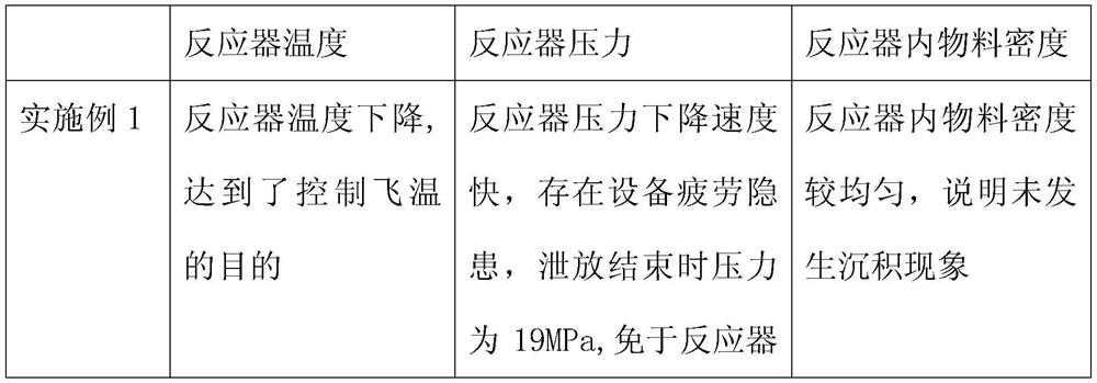
Embodiment 1
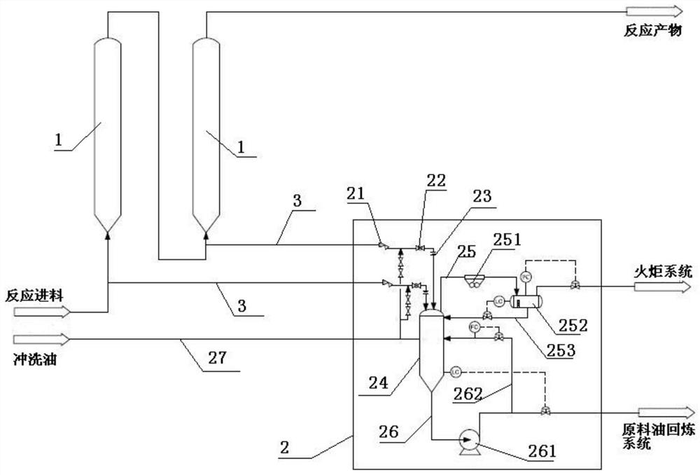
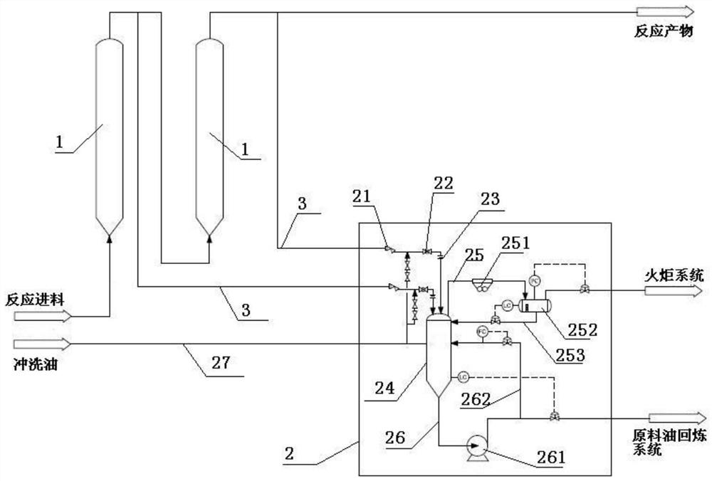
[0028] The suspended bed hydrogenation bleeding system described in this embodiment is as follows: figure 1As shown, a suspension bed hydrogenation reactor 1 is included, the top of the suspension bed hydrogenation reactor 1 is connected with a reaction product pipeline, and the bottom is connected with a reaction feed pipeline and a discharge pipeline 3, and the discharge pipeline 3 is connected to the The cooling separation system 2 is connected, and the cooling separation system 2 is respectively connected with the flare system and the raw material oil refining system, wherein, the cooling separation system 2 includes a discharge tank 24, and the top of the discharge tank 24 is connected to the discharge tank 24. The discharge pipeline 3 is connected, and a discharge valve group is arranged on the discharge pipeline 3; a discharge pipeline 25 is connected to the top of the discharge tank 24, and an emergency discharge air cooler 251 and an emergency air cooler 251 are connec...
Embodiment 2
[0031] The suspended bed hydrogenation release system described in this embodiment is as follows: figure 1 As shown, a suspension bed hydrogenation reactor 1 is included, the top of the suspension bed hydrogenation reactor 1 is connected with a reaction product pipeline, and the bottom is connected with a reaction feed pipeline and a discharge pipeline 3, and the discharge pipeline 3 is connected to the The cooling separation system 2 is connected, and the cooling separation system 2 is respectively connected with the flare system and the raw material oil refining system, wherein, the cooling separation system 2 includes a discharge tank 24, and the top of the discharge tank 24 is connected to the discharge tank 24. The discharge pipeline 3 is connected, and a discharge valve group is arranged on the discharge pipeline 3, and the discharge valve group includes a high-pressure RAM valve 21 and a high-pressure ball valve 22 arranged in sequence on the discharge pipeline 3. The p...
PUM
| Property | Measurement | Unit |
|---|---|---|
| Aperture | aaaaa | aaaaa |
| Thickness | aaaaa | aaaaa |
| The inside diameter of | aaaaa | aaaaa |
Abstract
Description
Claims
Application Information