High-sensitivity intelligent metal detector
A metal detector, high-sensitivity technology, used in instruments, measuring devices, scientific instruments, etc., can solve the problems of poor anti-electromagnetic interference, unreasonable process, poor anti-mechanical vibration ability, etc., and achieve strong anti-common mode interference ability. , The effect of strengthening environmental signal recognition and strong anti-electromagnetic interference ability
- Summary
- Abstract
- Description
- Claims
- Application Information
AI Technical Summary
Problems solved by technology
Method used
Image
Examples
Embodiment 1
[0051] Set the differential signal alarm threshold of the main control module according to the on-site working conditions, so that under normal working conditions, the probe will not alarm for normal electromagnetic field disturbances.
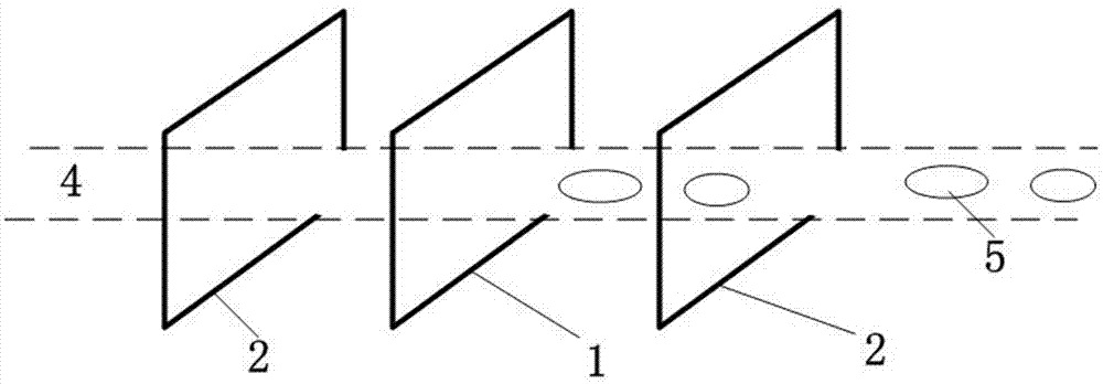
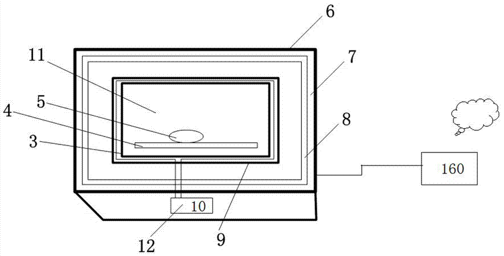
[0052] When the probe is working, the signal emitted by the transmitting coil is received by the receiving coils on both sides. When there is no object to be inspected in the detection channel, since the specifications of the two receiving coils are the same, the received signals are the same, and the probe does not alarm.
[0053] When the probe performs metal detection on the object to be inspected, the object to be inspected is sent into the detection channel by the conveyor belt; if there is a metal object in the object to be inspected, the signal emitted by the transmitting coil will reflect at the metal object and interfere with the electromagnetic field in the detection channel , So that the signals received by the first receiving coil and th...
Embodiment 2
[0055] The preset parameters and error balance of this product during implementation are as follows.
[0056] First test on-site assembly line working conditions and product characteristics to be inspected. Set and adjust the alarm threshold, amplification gain value, detection phase and other parameters of the main control module on the touch screen of the intelligent display terminal, so that under normal operating conditions, the probe will not alarm the common mode electromagnetic field disturbance.
[0057] When the pipeline is working, the signal transmitted by the transmitting coil is received by the receiving coils on both sides. When there is no object to be inspected in the detection channel, since the specifications of the two receiving coils are the same, the received signals are the same. Theoretically, the voltage difference between the two receiving coils If it is zero, the probe will not alarm. In fact, due to process and material errors, the difference value is no...
Embodiment 3
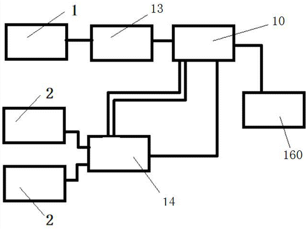
[0059] As described in Example 2, the main control module is based on the dsPIC chip. The sine wave is shaped by the PWM square wave sent by the dsPIC, or synthesized by the DDS chip set by the dsPIC through the serial port; the sine wave is formed by the BU407 power amplifier tube The push-pull circuit drives the transmitting coil to send out wireless signals; the receiving circuit takes AD817 as the core, and the signals of the two receiving coils are connected to the differential input of AD817, and then amplified and sent to the MC1496 multiplier for phase-sensitive detection. The main control chip dsPIC generates and transmits Two quadrature signals with the same frequency and a phase difference of 90 degrees are injected into the multiplier, and the received signal is multiplied separately, and the superimposed signal generated by the two metal foreign objects is separated by low-pass filtering, and then sent to multi-level signal amplification In the circuit, it is finall...
PUM
 Abstract
Description
Claims
Application Information
 - R&D
- Intellectual Property
- Life Sciences
- Materials
- Tech Scout
- Unparalleled Data Quality
- Higher Quality Content
- 60% Fewer Hallucinations
Browse by: Latest US Patents, China's latest patents, Technical Efficacy Thesaurus, Application Domain, Technology Topic, Popular Technical Reports.
© 2025 PatSnap. All rights reserved.Legal|Privacy policy|Modern Slavery Act Transparency Statement|Sitemap|About US| Contact US: help@patsnap.com


