Flue gas capture, transformation and application total recycling system in factories, power plants and refinery plants

A resource-based, flue gas technology, applied in the field of flue gas capture, to achieve the effects of large absorption capacity, high purification, and low energy consumption for regeneration

Active Publication Date: 2018-05-04
山西清洁碳经济产业研究院有限公司 +1
View PDF4 Cites 14 Cited by
  • Summary
  • Abstract
  • Description
  • Claims
  • Application Information

AI Technical Summary

Problems solved by technology

[0014] In order to solve the above-mentioned technical problems, the present invention provides a system for capturing, transforming and applying full-quantity resource utilization of factory, power plant and refinery flue gas. Aiming at the deficiencies in the prior art, the research and development and design of full-component, full-quantification, and comprehensive resource utilization of flue gas The combined technology of utilization and high value-added output; for the flue gas treatment of thermal power plants, thermal power plants, petroleum processing plants, steel plants, cement (phosphorus and magnesium) plants, chemical plants, etc. in the overall carbon dioxide emissions, especially the two major industries— Carbon dioxide in thermal power plants in the energy industry and petroleum processing plants in the industrial industry is used as a resource and converted into high value-added products to realize the transformation and application of absolute carbon dioxide emission reduction; develop innovative, low-cost, and high-efficiency carbon dioxide conversion technology, improve the conversion rate; apply carbon dioxide to manufacture high value-added products, cut off the source of scourge of smog and PM2.5, integrate solar and wind power generation systems, realize the closed cycle of carbon, renewable energy and fossil energy complement each other, and completely solve the problem of improvement Air pollution, global warming problem

Method used


Image

  • Flue gas capture, transformation and application total recycling system in factories, power plants and refinery plants
  • Flue gas capture, transformation and application total recycling system in factories, power plants and refinery plants
  • Flue gas capture, transformation and application total recycling system in factories, power plants and refinery plants

Examples


Embodiment Construction

[0138] The following will clearly and completely describe the technical solutions in the embodiments of the present invention with reference to the accompanying drawings in the embodiments of the present invention. Obviously, the described embodiments are only some, not all, embodiments of the present invention. Based on the embodiments of the present invention, all other embodiments obtained by persons of ordinary skill in the art without creative efforts fall within the protection scope of the present invention.

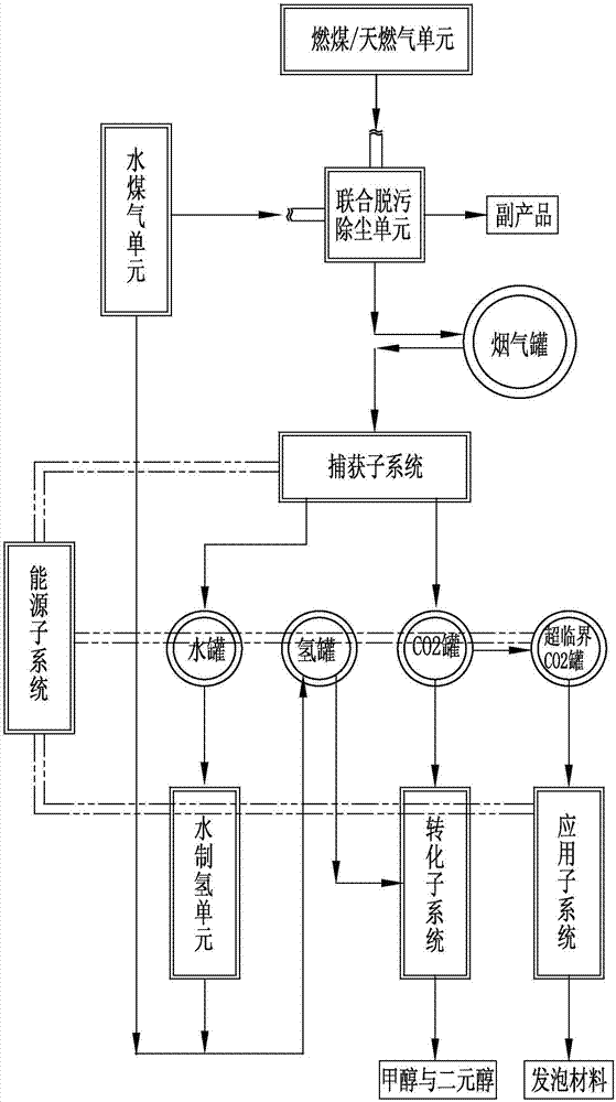
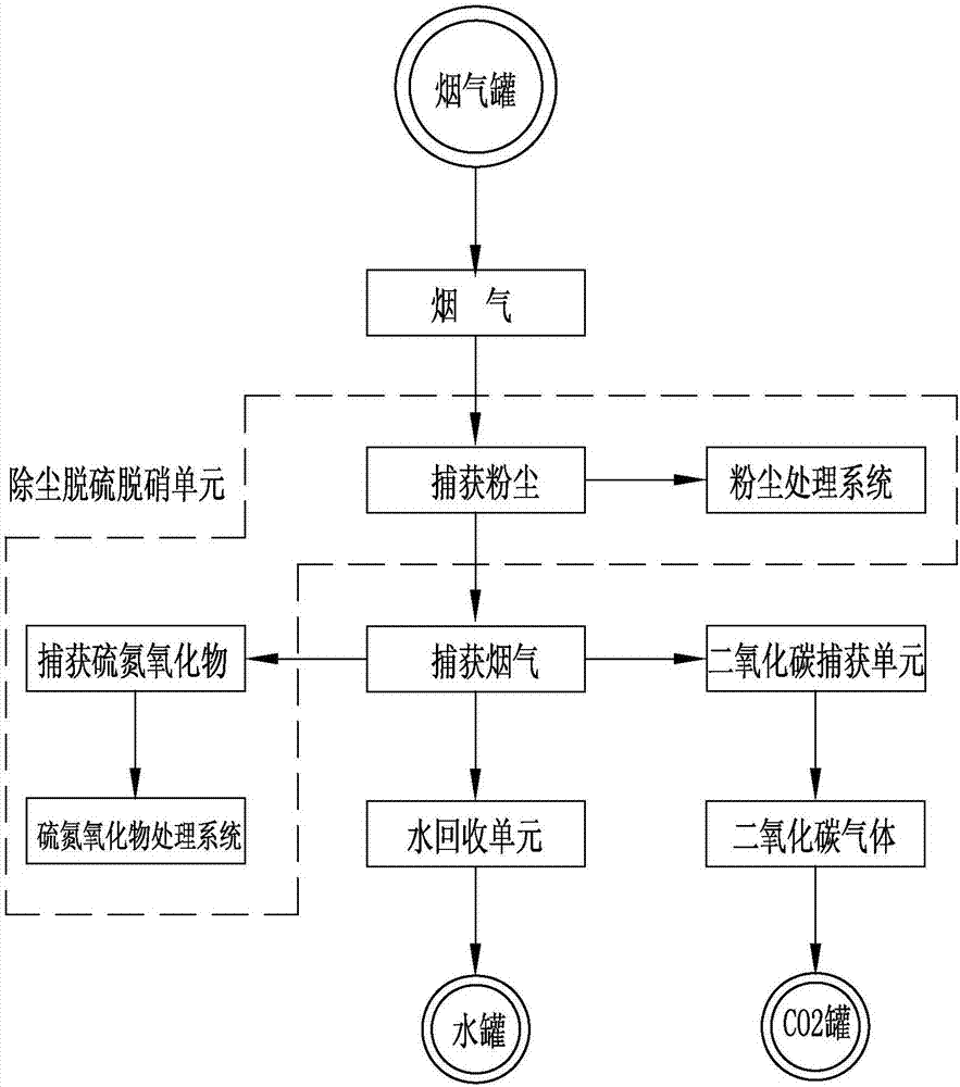
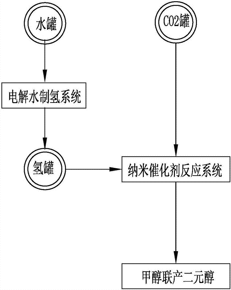
[0139] according to Figure 1 to Figure 10 , the present invention provides a system for the capture, conversion and utilization of flue gas in a factory, power plant and refinery, including a combined decontamination and dust removal unit, a hydrogen production unit, a capture subsystem, a transformation subsystem, an application subsystem, a water gas unit, a carbon dioxide Capture unit, water recovery unit, supercritical refining and preparation of nanocellulose...


PUM

PropertyMeasurementUnit
strengthaaaaaaaaaa
densityaaaaaaaaaa

Abstract

The invention discloses a flue gas capture, transformation and application total recycling system in factories, power plants and refinery plants. The operating method comprises the following steps: removing dust and oxides by virtue of a combined decontamination and dust removal unit; capturing CO2 by a capture subsystem, and recovering water by a water recovery unit; decomposing water into hydrogen and oxygen by a hydrogen production unit, and combustion-supporting by an oxygen feed water gas unit toobtain the hydrogen; carrying out a catalytic reaction on the CO2 and hydrogen to be transformed into methanol and dihydric alcohol by a transformation subsystem; preparing supercritical CO2 nano-cellulose paste by an application subsystem, blending and extruding material particles to become asupercritical CO2 nano-cellulose foam material; and connecting an energy subsystem to solar wind power, and supplementing energy by virtue of waste heat and hydrogen power generation. According to the system disclosed by the invention, a combined technology for total-component, total-dose integrated recycling and high value-added production of the flue gas is designed for the first time; the fluegas is transformed into the methanol, dihydric alcohol and the ultra-light super-strong nano-cellulose foam material, and absolute reduction, transformation and application of the CO2 can be realized; and the problems of atmospheric pollution and greenhouse effects are completely improved.

Description

technical field [0001] The invention relates to the field of flue gas capture, carbon dioxide conversion and application technical equipment, in particular to a system for capturing, converting and applying full-quantity resource utilization of flue gas in factories, power plants and refineries. Background technique [0002] Since the middle of the 20th century, more than half of global warming has been caused by human activities, and the reliability of this conclusion is over 95%. There is no doubt about global warming in the past century. From 1880 to 2012, the average global surface temperature increased by 0.85 degrees Celsius; in the northern hemisphere, the period from 1983 to 2012 may be the warmest 30 years in the past 1400 years. In the past 60 years, the average surface temperature in China has risen by 1.38 degrees Celsius, an average increase of 0.23 degrees Celsius every 10 years, almost twice the global rate. In recent years, global high-temperature events hav...

Claims


Application Information

Patent Timeline
Patent Type & Authority Applications(China)
IPC IPC(8): B01D53/14C07D317/38C07C29/136C07C31/04C07C31/20C08J9/12C08L1/02
CPCB01D53/1418B01D53/1475B01D53/1493C07C29/136C07D317/38C08J9/122C08J2301/02C08J2203/06C08J2203/08C07C31/04C07C31/20Y02B30/52Y02P20/50Y02E60/32Y02T10/12Y02P20/54C07C31/202F02M21/0215F02M21/0218B01D2258/0283F23C9/00
Inventor 宋维宁
Owner 山西清洁碳经济产业研究院有限公司
Why Eureka
Try Eureka