Device for real-time non-contact measurement and compensation of skin topography error in mirror milling and precise control method for skin thickness

A non-contact measurement and skin thickness technology, which is applied in the direction of program control, computer control, general control system, etc., can solve the problems of inability to perform online compensation, large amount of measured data, and large skin size, so as to reduce data Treatment, improve processing efficiency, and control the effect of small difficulty

Active Publication Date: 2020-09-29
DALIAN UNIV OF TECH
View PDF8 Cites 0 Cited by
  • Summary
  • Abstract
  • Description
  • Claims
  • Application Information

AI Technical Summary

Problems solved by technology

[0005] The existing technology has the following disadvantages: due to the large size of the skin and the large amount of measured data, during laser scanning, only limited points are measured to obtain the actual surface point cloud data of the skin, and the data is processed and analyzed. Fitting, forming the actual profile, low precision
In addition, the existing process flow has no actual thickness information before skin milling. Although mirror milling can guarantee equal thickness processing, the support surface is often quite different from the theoretical model.
When ultrasonic thickness measurement is performed online, there will be separation between the support column and the workpiece, resulting in loss of thickness data and inability to perform online compensation

Method used


Image

  • Device for real-time non-contact measurement and compensation of skin topography error in mirror milling and precise control method for skin thickness
  • Device for real-time non-contact measurement and compensation of skin topography error in mirror milling and precise control method for skin thickness
  • Device for real-time non-contact measurement and compensation of skin topography error in mirror milling and precise control method for skin thickness

Examples


Embodiment 1

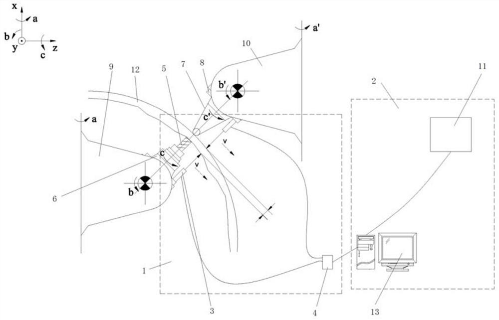
[0037] Such as figure 1 As shown in the figure, a real-time non-contact measurement and compensation device for surface error in mirror milling, including a non-contact measurement module 1 and a data processing compensation module 2;

[0038] The non-contact measurement module 1 includes two laser displacement sensor heads 3 and a laser displacement sensor controller 4 for collecting measurement data of the two laser displacement sensor heads 3;

[0039]The two laser displacement sensor heads 3 are respectively fixed on the milling cutter connection plate 6 (for the c-axis of the mirror image milling machine tool) with the milling cutter 5 and the support column connection plate 8 with the support column 7 (for the c’ axis of the mirror image milling machine tool). shaft), the milling cutter connecting disc 6 and the supporting column connecting disc 8 are respectively connected with the processing head 9 of the mirror image milling machine tool and the supporting head 10 of ...

Embodiment 2

[0043] Such as Figure 1-Figure 4 As shown, a method for accurately controlling the skin thickness according to the real-time non-contact measurement and compensation device of the mirror image milling skin topography error described in Embodiment 1 has the following steps:

[0044] S1. Generate a processing trajectory program according to processing requirements;

[0045] S2. Set the initial cutting depth of the milling cutter 5, and start the machining trajectory program;

[0046] S3. Initialize the distance between the measurement points of the two laser displacement sensor heads 3;

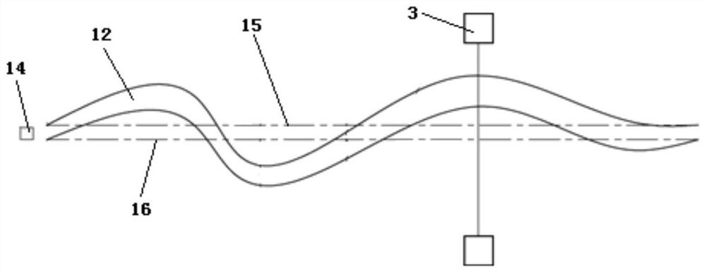
[0047] S4. Let the plane passing through the support point between the support column 7 and the skin 12 and perpendicular to the axis of the milling cutter 5 be the support surface, and the straight line is along the axis of the milling cutter 5 relative to the skin 12 The processing track moves synchronously, the two laser displacement sensor heads 3 measure the skin 12 from the initial pos...


PUM


Abstract

The invention discloses a real-time noncontact measurement and compensation device for a mirror image milling processing error of skin shape, and a skin thickness precise control method. The device comprises a noncontact measurement module and a data processing compensation module. The noncontact measurement module comprises two laser displacement sensor heads and a laser displacement sensor controller which collects the measurement data of the two laser displacement sensor heads. The data processing compensation module comprises a built-in coordinate bias module of a machine tool numerical control system, and a data analysis module which carries out the processing of the measurement data and calls the built-in coordinate bias module of the machine tool numerical control system to achievethe automatic compensation of the skin deformation in processing according to a processing result. The device just needs to store the dynamic measurement data between a measurement point and a processing point at one moment, reads data, generates a compensation value, then carries out the processing of the compensation value, releases the store space of the data, is small in stored data size, avoids the processing and fitting of the point cloud data of the whole skin, and greatly reduces the data processing and feedback control time.

Description

technical field [0001] The present invention relates to a device and method for precisely controlling the thickness of mechanical processing, in particular to a device and method for precisely controlling the thickness of mirror image milling, in particular to a device for real-time non-contact measurement and compensation of skin shape errors during mirror image milling And the precise control method of skin thickness. Background technique [0002] Mirror milling technology is a new technology for CNC milling of aircraft skins. The mirror milling system consists of two five-coordinate horizontal machine tools that move synchronously. The main shaft of one of the horizontal machine tools is the processing head, and the milling cutter is installed to process the skin. The main shaft of the other five-axis machine tool is the supporting head, and the supporting column is installed to support the skin. The milling cutter and the supporting column move synchronously on the same ...

Claims


Application Information

Patent Timeline
Patent Type & Authority Patents(China)
IPC IPC(8): G05B19/401
CPCG05B19/401G05B2219/37398
Inventor 董志刚康仁科鲍岩王昌瑞朱祥龙付海洋
Owner DALIAN UNIV OF TECH
Why Eureka
Try Eureka