
Flue gas desulfurizing system and method using flue gas desulfurizing system to desulfurize flue gas

A desulfurization system and flue gas technology, applied in the field of flue gas desulfurization system and flue gas desulfurization, can solve the problems of excessive and unsatisfactory emissions, and achieve the effects of clean flue gas, strong absorption capacity and low technology investment

Active Publication Date: 2018-05-29
SINOPEC NANJING ENG & CONSTR +1
View PDF2 Cites 10 Cited by
  • Summary
  • Abstract
  • Description
  • Claims
  • Application Information

AI Technical Summary

Problems solved by technology

Since the improved CLAUS sulfur recovery technology realized industrial production in the 1930s, after nearly 90 years of development and improvement, it has become mature and perfect. The emission concentration of sulfur dioxide in the air is usually 300-800mg / Nm 3 , cannot meet the current standard requirements
[0003] At present, the commonly used transformation technologies for tail gas treatment of sulfur recovery units are: replacing high-efficiency Claus catalysts, adding bubblers in liquid sulfur tanks, replacing solvents in solvent regeneration systems, and adding alkali washing tower facilities before incineration. After these technological transformations, the smoke The emission concentration of sulfur dioxide in the air basically reaches 100mg / Nm 3 Below, but in abnormal circumstances such as the start-up period of the device, start-up pre-vulcanization, stoppage of sulfur blowing, by-pass conditions, and short-term large fluctuations in raw materials during normal production, there are still problems of excessive emissions

Method used


Image

  • Flue gas desulfurizing system and method using flue gas desulfurizing system to desulfurize flue gas
  • Flue gas desulfurizing system and method using flue gas desulfurizing system to desulfurize flue gas

Examples


Embodiment 1

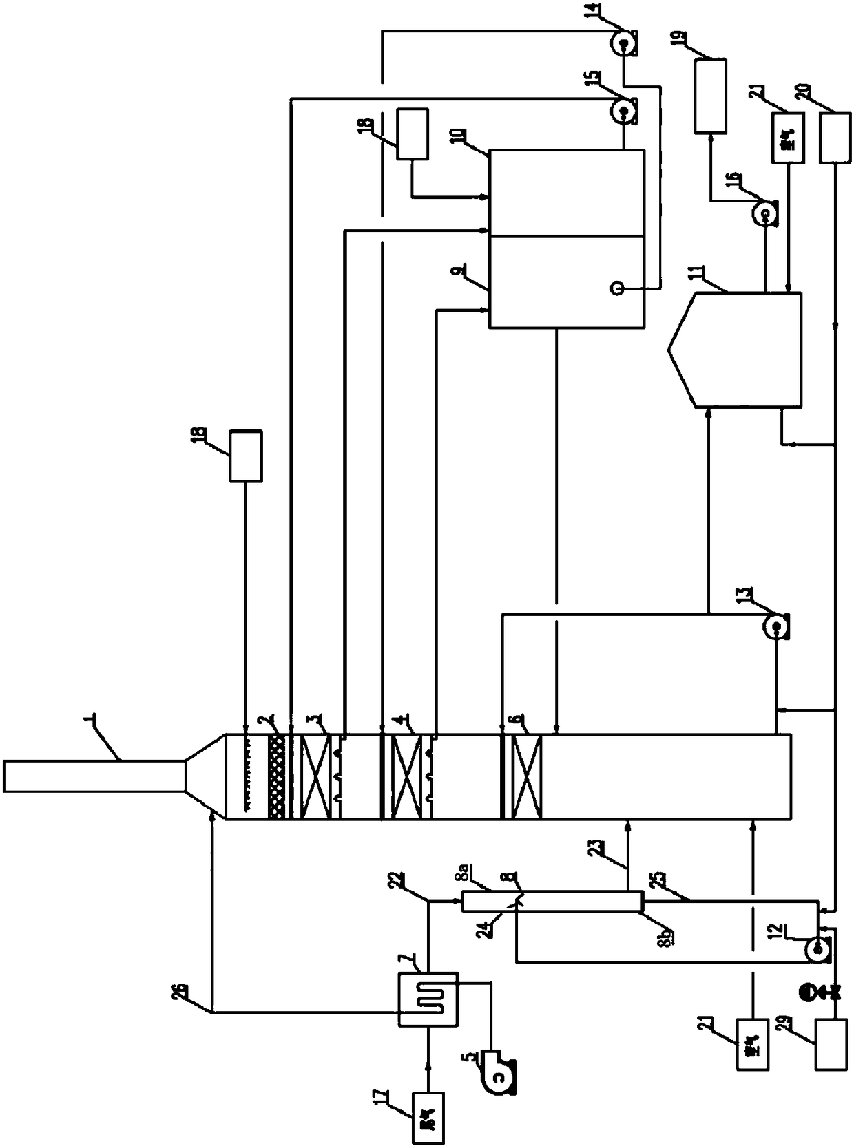
[0035] Such as figure 1 As shown, a flue gas desulfurization system includes a quenching section 8, an absorption section and a chimney 1.

[0036] The quenching section 8 is composed of a spray area 8a and a liquid storage tank 8b which communicate with each other. The spray area 8a includes a tubular shell and a spray layer 24, and the tubular shell is a vertical pipe; the liquid storage tank 8b is located at the bottom of the quenching section 8. In the quenching section 8, the spraying area 8a is provided with a spraying layer 24 at the entrance of the flue gas, and the quenching circulating liquid sprayed from the spraying layer 24 has the same flow direction as the flue gas in the spraying area 8a, and the quenching circulating liquid and the flue gas The gas is in contact with the flow. The bottom of the liquid storage tank 8b is provided with a quenched circulating liquid outlet, and the spray layer 24 is connected with the quenched circulating liquid outlet at the bo...

Embodiment 2

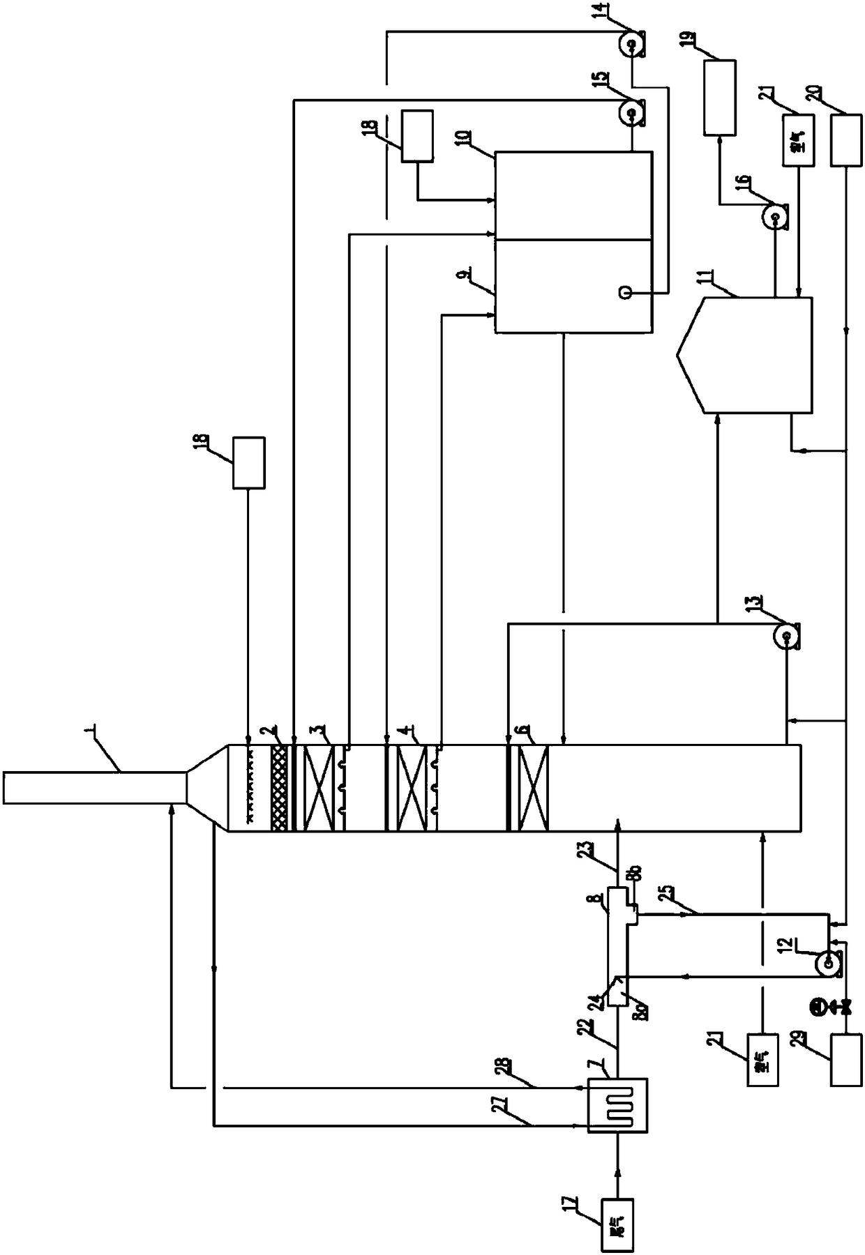
[0064] Such as figure 2 As shown, in addition to replacing the vertical tubular shell of the spray area 8a in Embodiment 1 with a horizontal tubular shell, the exhaust gas flows horizontally in the spray area 8a, the gas-liquid in the spray area 8a is countercurrently contacted, and the exhaust gas The waste heat exchanges heat with the purified flue gas 27 at the top of the tower, so that the temperature of the purified flue gas at the top of the tower is raised to 110-220°C to obtain hot flue gas 28, and then the hot flue gas 28 is discharged to the atmosphere through the chimney, and the rest are the same as in Example 1. This will not be repeated here.


PUM


Abstract

The invention discloses a flue gas desulfurizing system. The flue gas desulfurizing system comprises a chilling section and an absorbing section which are mutually communicated by a connecting pipe, wherein the chilling section comprises a spraying area and a liquid storage tank which are mutually communicated; the spraying area is provided with a spraying layer, the liquid storage tank is positioned under the spraying area, and the spraying layer and the bottom part of the liquid storage tank are connected by a pipeline and a chilling circulation pump to form a chilling loop; a pipeline for connecting the chilling circulation pump and the liquid storage tank is provided with an alkaline liquid inlet, and the alkaline liquid inlet is connected with an alkaline liquid storage tank through aswitch valve. The invention also provides a method using flue gas desulfurizing system to desulfurize flue gas. The flue gas desulfurizing system has the advantages that the high-temperature tail gaswith higher concentration of SO2 (silicon dioxide) can be treated, the investment is low, the energy consumption is low, and the clean and environment-friendly effects are realized. A method has theadvantages that the operation is simple, the absorbing ability is strong, and the scaling and blockage of equipment can be avoided; the higher desulfurizing rate can be obtained with fewer circulationliquid, the exhausted flue gas is clean, any inorganic particulate matter is basically not contained, the trailing white smoke is avoided, and the haze weather is not formed.

Description

technical field [0001] The invention relates to sulfur-containing flue gas treatment, in particular to a flue gas desulfurization system and a method for using the flue gas desulfurization system to carry out flue gas desulfurization. Background technique [0002] With the massive development of sour crude oil and natural gas resources in the world, and the continuous development of coal chemical industry, sulfur recovery has become an indispensable supporting environmental protection device; my country has always advocated energy conservation and emission reduction work, and sulfur dioxide pollutes the environment seriously, and smog is also It is getting more and more serious. With the stricter and higher emission standards, we are required to continuously improve the sulfur recovery process, especially the advanced tail gas treatment technology to reduce SO 2 emission and protect our environment. The "Petroleum Refining Industry Pollutant Discharge Standard" (GB 31570-201...

Claims


Application Information

Patent Timeline
Patent Type & Authority Applications(China)
IPC IPC(8): B01D53/50B01D53/78B01D53/96F23J15/06
CPCB01D53/502B01D53/504B01D53/78B01D53/96B01D2251/304B01D2258/0283F23J15/06
Inventor 李明军邢亚琴刘芳张传玲
Owner SINOPEC NANJING ENG & CONSTR
Learn More