Ultrahigh-speed laser cladding technology

A laser cladding and ultra-high-speed technology, which is applied in the coating process of metal materials and coatings, can solve the problems of low powder utilization, large heat input, and reduced processing efficiency, and achieve high interface bonding strength and heat input. Small amount, stable powder feeding effect

Inactive Publication Date: 2018-06-01
ADVANCED MFG TECH CENT CHINA ACAD OF MASCH SCI & TECH
View PDF2 Cites 27 Cited by
  • Summary
  • Abstract
  • Description
  • Claims
  • Application Information

AI Technical Summary

Problems solved by technology

Due to the large number of pores in the coating prepared by thermal spraying, it must be prepared by multi-layer deposition (each layer is about 25-50 μm thick), resulting in reduced processing efficiency
In addition, the consumption of powder materials and gas in the processing process is relatively large, and the maximum utilization rate of materials is only about 50%.
[0005] 3. Overlay welding technology. The coating of this technology is generally thicker (about 2~3mm), but the parts need to be preheated, the heat input is large, and the heat-affected zone is large, resulting in large deformation of the parts and a decline in mechanical properties.
[0006] 4. Laser cladding technology, see figure 2 , this traditional technology has the advantages of high bonding strength, small heat quantity, small deformation, etc., and can obtain the required cladding layer properties by adjusting the powder composition, so it has begun to be applied in many industries, but the processing efficiency of this technology is low. The cladding rate is generally 0.5~3m / min, the powder utilization rate is low, generally about 50%, and the laser energy is focused on the matrix material, and the powder is mixed and bonded by melting the matrix material, which makes the laser energy utilization efficiency and cladding The rate is low, the powder is still a solid particle when combined with the base material, and the surface smoothness of the finished product is poor

Method used


Image

  • Ultrahigh-speed laser cladding technology
  • Ultrahigh-speed laser cladding technology
  • Ultrahigh-speed laser cladding technology

Examples


Embodiment 1

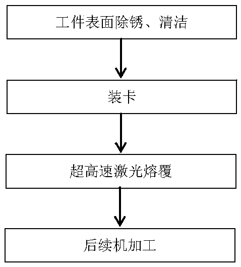
[0041] see figure 1 , providing an ultra-high-speed laser cladding process, specifically adopting the following steps:

[0042] (1) Use sandpaper to wipe and clean the rust spots on the surface of the workpiece to be clad, and clean them with alcohol;

[0043] (2) Load the workpiece into the ultra-high-speed laser cladding machine tool, and clamp it with the chuck;

[0044] (3) Alloy powder for ultra-high-speed laser cladding is used as the cladding material;

[0045] (4) Adjust the Z direction knob of the laser cladding head, set the laser defocus amount to 1~2mm, and the spot size Φ1.0~Φ1.5mm; adjust the X axis of the machine tool (the radial direction of the workpiece) so that the distance between the powder feeding head and the surface of the workpiece is 10~13mm , the powder focus point is 0.2~2mm away from the workpiece surface, and the powder spot size is Φ0.5~1mm;

[0046] (5) Adjust the speed of the powder feeding plate of the powder feeder to control the powder f...

Embodiment 2

[0056] The present invention also provides an ultra-high-speed laser cladding process, which is characterized in that it comprises the following steps:

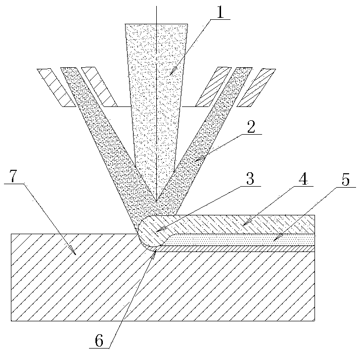
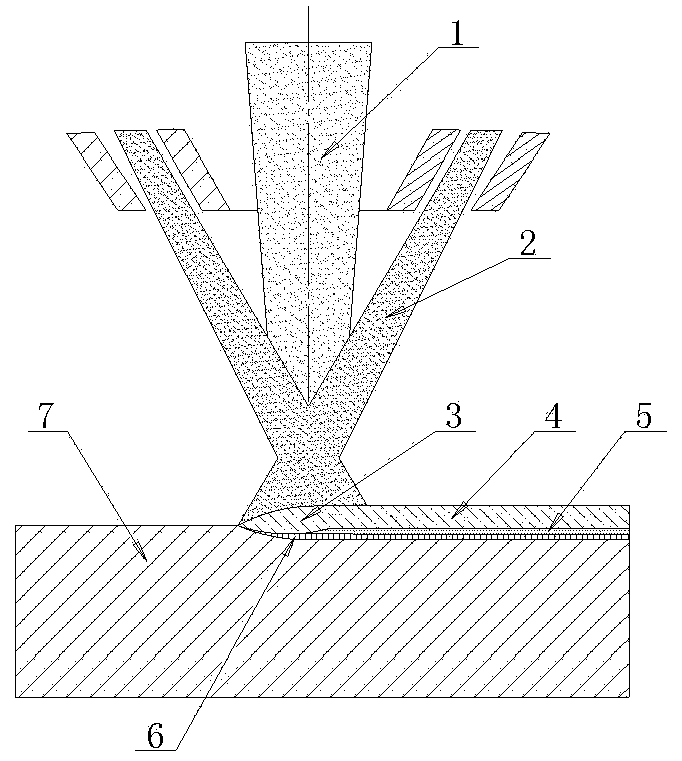
[0057] A small part of the energy of the laser is controlled to act on the upper surface of the base material to form a shallow molten pool 3, and most of the energy of the laser is applied to the alloy powder above the base material;

[0058] The temperature of the alloy powder rises to the melting point and melts before entering the molten pool 3, and drops into the molten pool 3 in the form of droplets to combine with the matrix material.

[0059] It is understandable that since the traditional process focuses the laser energy on the matrix material to melt the dense matrix itself, under the same laser energy, the time it takes to melt the matrix needs to be greatly increased, which greatly limits The cladding speed reduces the utilization rate of the powder. On the contrary, in the present invention, the laser energy is s...

Embodiment 3

[0065] Embodiment 3: This example illustrates the ultra-high-speed laser cladding process of the present invention by taking a columnar part as an example. The base material of the workpiece is 27SiMn, and the size is Φ100mm in diameter x 1000mm in length.

[0066] An ultra-high-speed laser cladding process, specifically adopting the following steps:

[0067] (1) Use sandpaper to wipe and clean the rust spots on the surface of the workpiece to be clad, and clean them with alcohol;

[0068] (2) Load the workpiece into the ultra-high-speed laser cladding machine tool, and clamp it with the chuck and the top;

[0069] (3) The alloy powder for ultra-high-speed laser cladding is used as the cladding material. The mass percentage of the alloy composition is: Cr 16.0%~18.0%, Ni 10.0%~14.0%, Mo 2.0%~3.0%, Mn<2.0%, C≤0.03%, Si≤1.0%, P≤0.045%, S≤0.03%, the rest is Fe; the powder particle size range is 15~45μm, sphericity≥90%, oxygen content≤150ppm, fluidity≤20s / 50g , Hollow powder rat...


PUM

PropertyMeasurementUnit
oxygen contentaaaaaaaaaa
fluidityaaaaaaaaaa
thicknessaaaaaaaaaa

Abstract

The invention belongs to the field of laser processing, and particularly relates to an ultrahigh-speed laser cladding technology. The ultrahigh-speed laser cladding technology is characterized in thatultrahigh-speed laser cladding linear velocity is acquired through high-speed rotation of a workpiece, and a compact cladding layer is formed on the surface of the workpiece through interaction of laser and powder and adjustment and matching of technological parameters. Compared with traditional laser cladding, the ultrahigh-speed laser cladding technology has the advantages that efficiency is improved by 10 times, the obtained cladding layer is formed through complete metallurgical bonding, surface finish is high, the material utilization rate is high, energy consumption is low, production cost can be greatly reduced, and production efficiency is improved.

Description

technical field [0001] The invention relates to an ultra-high-speed laser cladding process, which belongs to the field of laser processing. Background technique [0002] In the field of construction machinery, many shaft metal components have requirements for corrosion resistance and wear resistance on the surface, and require special treatment. The common treatment processes are as follows. [0003] 1. Electroplating technology. This technology has a thin coating, generally no more than 100 μm. Therefore, under special working conditions, it is easy to cause the entire part to fail due to local coating damage. Moreover, the bonding force between the coating and the substrate is weak, generally no more than 100MPa, and the corrosion resistance is poor, and it is easy to peel off. It also causes serious waste of resources and environmental pollution, which is an industry that urgently needs to be relieved. [0004] 2. Thermal spraying technology, this technology is mechanic...

Claims


Application Information

Patent Timeline
Patent Type & Authority Applications(China)
IPC IPC(8): C23C24/10
CPCC23C24/106
Inventor 王淼辉葛学元杜博睿范斌郭瑞峰梁金明
Owner ADVANCED MFG TECH CENT CHINA ACAD OF MASCH SCI & TECH
Why Eureka
Try Eureka