Method and device for the additive manufacturing of components

A technology of additive manufacturing and components, applied in the direction of additive manufacturing, processing manufacturing, manufacturing tools, etc., to achieve the effect of expanding technical capabilities, reducing investment, and reducing energy consumption

Active Publication Date: 2018-06-08
阿迪鲁特有限责任公司
View PDF10 Cites 8 Cited by
  • Summary
  • Abstract
  • Description
  • Claims
  • Application Information

AI Technical Summary

Problems solved by technology

[0011] Regardless of all the advantages of this manufacturing option, there are some disadvantages, the main reason being that the material is fed into the pool melt with an air flow through the nozzle

Method used


Image

  • Method and device for the additive manufacturing of components
  • Method and device for the additive manufacturing of components
  • Method and device for the additive manufacturing of components

Examples


Embodiment Construction

[0039] The disclosed methods for forming additive parts and their implementing devices are related to each other through a common invention design, and are illustrated by the following specific application examples.

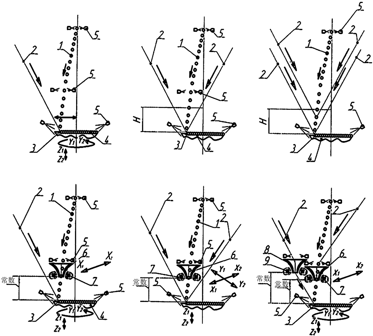
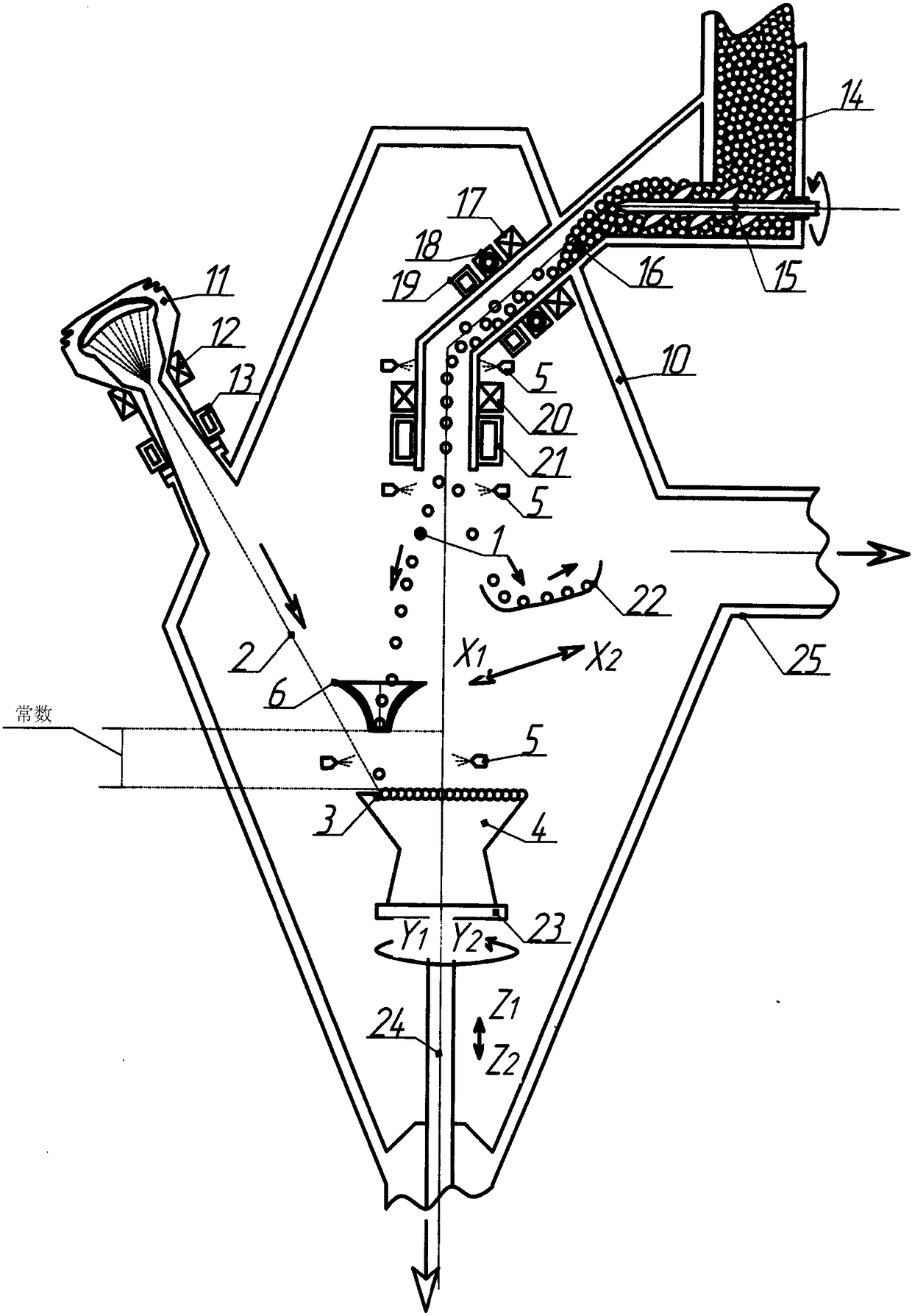
[0040] figure 2 The main proposed method of manufacturing a component 4 is shown in which direct particles 1 are deposited into a molten pool melt 3 formed by a jet 2 , where a material falling path is formed under an electromagnetic field and monitored by a sensor 5 throughout the movement path, The sensor 5 can be used as a radar, scanner, pyrometer, spectrometer, etc. when required.

[0041] figure 2 a shows the use of a jet 2 to generate a molten pool melt 3 in the body of a component 4 formed by particles 1 falling from a height under the action of gravity and controlled by an electromagnetic field. Sensors 5 are installed along the particle movement path; they determine the coordinates of the particle at a specific moment, its speed, direction, temperat...


PUM


Abstract

The invention relates to the field of the additive manufacturing of components, which are formed by the direct deposition of a substance, in the form of granules of a metal or non-metal, which passesfrom a reservoir into a melt bath, produced by the thermal energy of a laser or electron beam, and subsequently crystallizes. The granules enter the melt bath without the intervention of a gas stream,the path and rate of travel of said granules changing while they are in flight under the effect of an electromagnetic field. The granules travel within a chamber, falling into the melt bath from above from a reservoir, from which they are fed at a set speed by the rotation of an adjustable screw feed, and passing through a system of electromagnetic devices, which control the path of the granulesby means of electromagnetic fields. The coordinates of this path are tracked by sensors, which transmit a signal to a computer, wherein the flight path of the granules is adjusted by control via the electronic devices and the delivery speed and volume of the substance is adjusted by adjusting the rotation of the screw feed. The invention increases the efficiency of the production cycle, reduces the dimensions of the equipment and increases the accuracy and speed with which material is delivered for the manufacture of a component, while enabling adjustment of the amount, temperature, path and fraction of said material and increasing the strength of the component.

Description

technical field [0001] The proposed group of inventions relates to the field of additive manufacturing and can be used to manufacture any part made of metal, non-metal and various materials. Background technique [0002] [1]. Selective Laser Sintering (SLS) or Electron Beam Melting (EBM) as a prototype of the present invention, in which objects are formed from fusible powder materials (plastics, metals, ceramics) by melting them under laser or electron radiation. [0003] figure 1 Shown is the selective melting process of a powder (granule) 1, laminated on a plane in the form of a roll, which is selectively melted by a beam 2 of photons or electrons and produces a molten pool melt 3 of depth N. The molten pool melt penetrates the top layer of particles and into the body of the part 4 to a depth n, ie the top layer of particles fuses with the bottom layer of previously melted particles representing the top surface of the body of the part. [0004] Despite the significant ad...

Claims


Application Information

Patent Timeline
Patent Type & Authority Applications(China)
IPC IPC(8): B22F3/105B33Y10/00B33Y30/00
CPCB33Y10/00B33Y30/00B22F2999/00B23K26/342B23K15/0086Y02P10/25B22F10/25B22F12/90B22F3/105B29C64/329B29C64/153B29C64/188B23K26/1464
Inventor A·E·沃尔科夫
Owner 阿迪鲁特有限责任公司
Why Eureka
Try Eureka