
Method for preparing vanadium dioxide film through magnetron sputtering at low temperature

A technology of vanadium dioxide and magnetron sputtering, which is applied in sputtering coating, metal material coating process, vacuum evaporation coating, etc., can solve the problems of low production efficiency and slow deposition rate, and achieve energy saving, The effect of reducing the preparation temperature and good thermochromic performance

Active Publication Date: 2018-06-29
SHANGHAI INST OF CERAMIC CHEM & TECH CHINESE ACAD OF SCI
View PDF7 Cites 5 Cited by
  • Summary
  • Abstract
  • Description
  • Claims
  • Application Information

AI Technical Summary

Problems solved by technology

[0004] In the literature report on reducing the sputtering temperature, the Chinese patent "A Preparation Method of Vanadium Dioxide Film" (application publication number CN 103014701 A) discloses a method of using atomic layer deposition to obtain vanadium dioxide at a lower temperature Thin film technology, the substrate temperature during the preparation process is 300-350 °C, but the deposition rate of the atomic layer deposition method is relatively slow compared with the magnetron sputtering method, and the production efficiency is extremely low

Method used


Image

  • Method for preparing vanadium dioxide film through magnetron sputtering at low temperature
  • Method for preparing vanadium dioxide film through magnetron sputtering at low temperature
  • Method for preparing vanadium dioxide film through magnetron sputtering at low temperature

Examples


Embodiment 1

[0040] The substrate is ordinary float glass or quartz glass. The substrate was ultrasonically cleaned with acetone, isopropanol, and deionized water for 5 minutes, then dried with a nitrogen gun, fixed on the sample stage, and placed in a transitional vacuum chamber for vacuuming. The pumping is below 5Pa, and the glass substrate is introduced into the sputtering chamber through the pneumatic transfer rod. Turn on the substrate heating system, heat the glass sheet to 190°C, and keep the temperature constant.

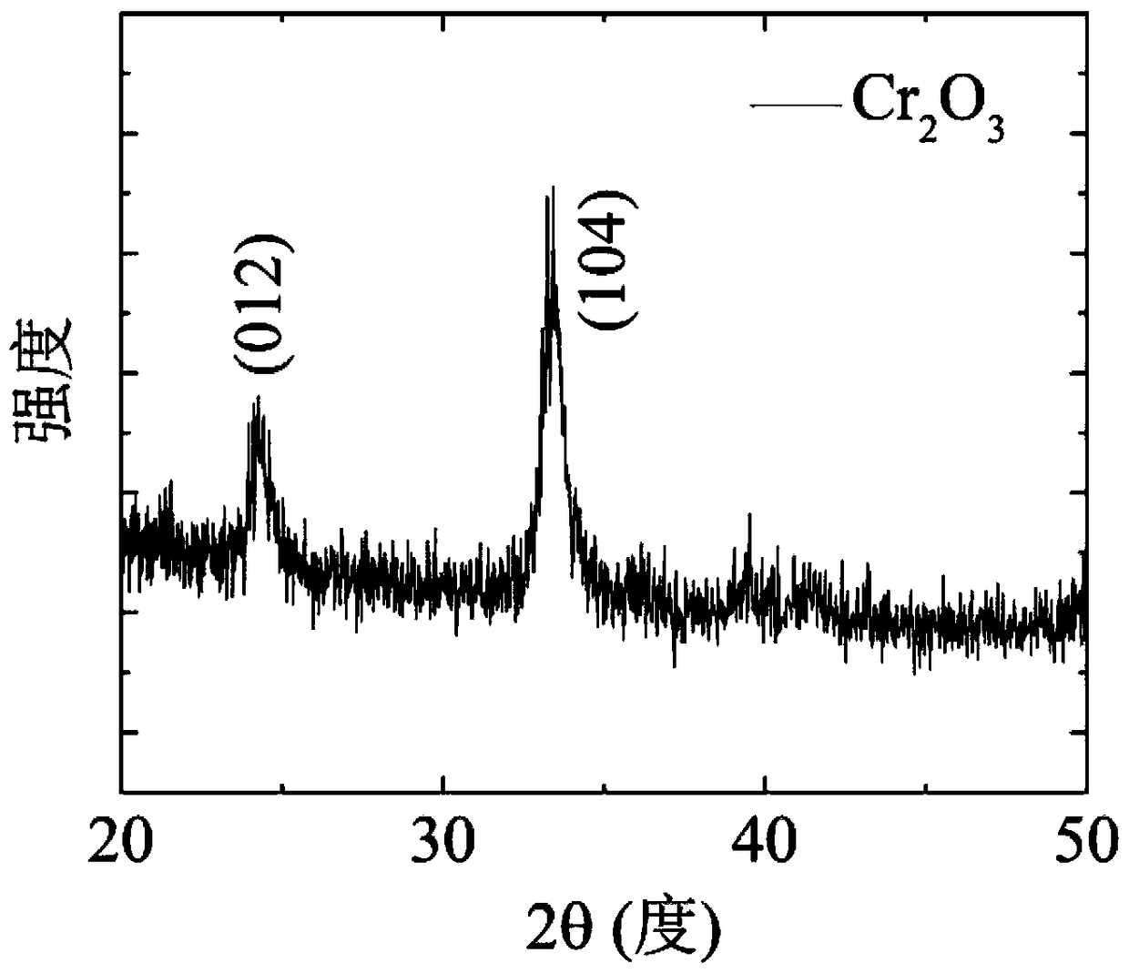
[0041] Cr first 2 o 3 The preparation of the buffer layer, the preparation conditions are as follows: use Cr 2 o 3 Ceramic target, the working atmosphere is high-purity Ar gas (purity higher than 99.999%), injected into the sputtering chamber at a gas flow rate of 50sccm, the working pressure is kept at 0.5Pa, the RF sputtering power is set to 120w, and the sputtering time is 40 Minutes, at this time the Cr on the glass substrate 2 o 3 The thickness is about 30nm...

Embodiment 2

[0044] The substrate is ordinary float glass or quartz glass. The substrate was ultrasonically cleaned with acetone, isopropanol, and deionized water for 5 minutes, then dried with a nitrogen gun, fixed on the sample stage, and placed in a transitional vacuum chamber for vacuuming. The pumping is below 5Pa, and the glass substrate is introduced into the sputtering chamber through the pneumatic transfer rod. Turn on the substrate heating system, heat the glass sheet to 150°C, and keep the temperature constant.

[0045] Cr first 2 o 3 The preparation of the buffer layer, the preparation conditions are as follows: use Cr 2 o 3 Ceramic target, the working atmosphere is high-purity Ar gas (purity higher than 99.999%), injected into the sputtering chamber at a gas flow rate of 50sccm, the working pressure is kept at 0.5Pa, the RF sputtering power is set to 120w, and the sputtering time is 40 Minutes, at this time the Cr on the glass substrate 2 o 3 The thickness is about 30nm...


PUM

PropertyMeasurementUnit
Roughnessaaaaaaaaaa
Roughnessaaaaaaaaaa

Abstract

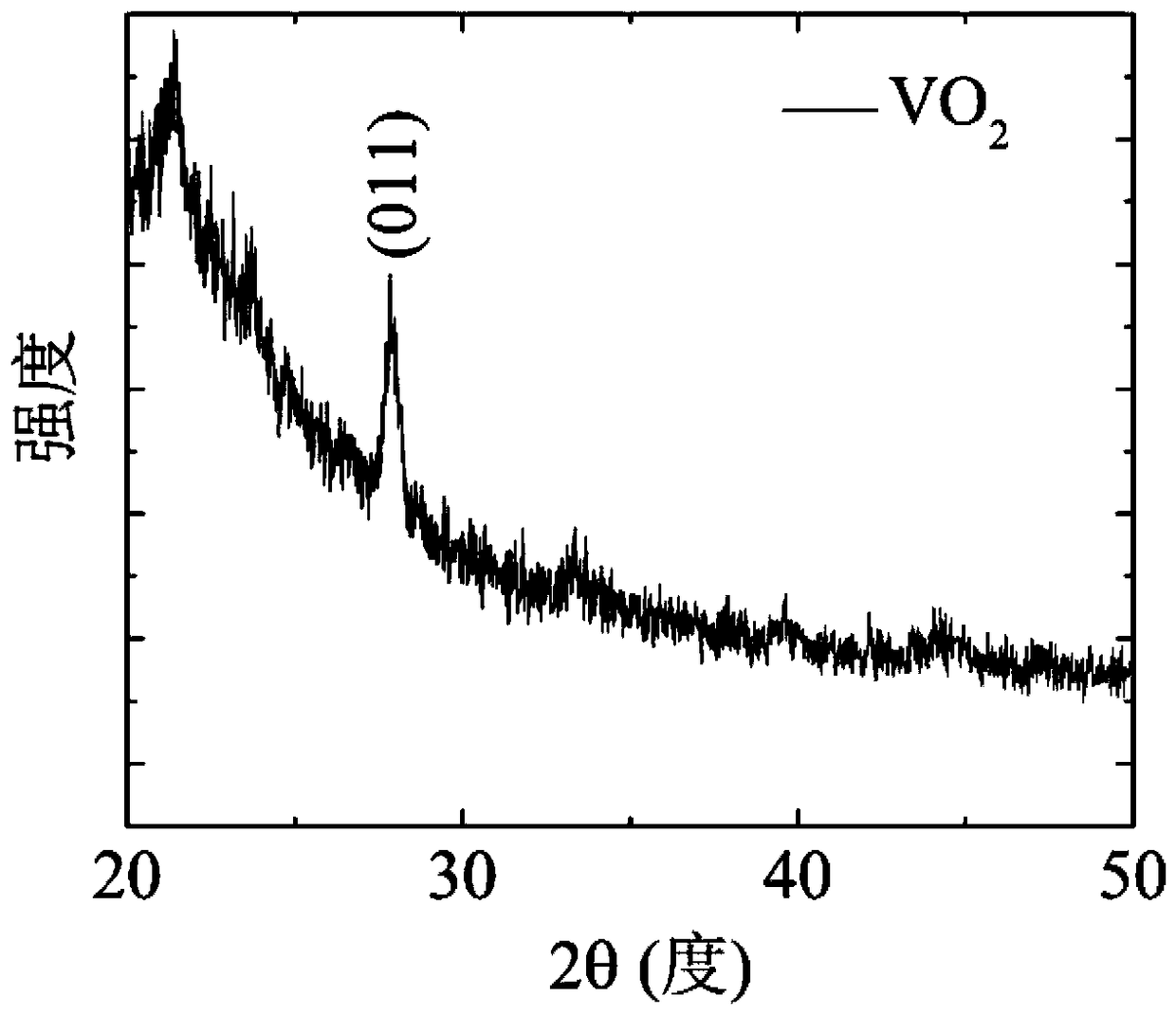
The invention relates to a method for preparing a vanadium dioxide film through magnetron sputtering at a low temperature. According to the method, the vanadium dioxide film is formed on a substrate with a Cr2O3 layer through magnetron sputtering, and the temperature of the substrate is 200 DEG C or below, optimally, 150 DEG C-200 DEG C. The Cr2O3 layer (the Cr2O3 buffer layer) material adopted inthe method is transparent in a visible light area and low in crystallization temperature, the lattice constant and the structure are matched with those of VO2 well, the Cr2O3 layer material can playa role of a template in growth induction in the growing process of vanadium dioxide, and therefore the preparation temperature of a VO2 film can be remarkably reduced.

Description

technical field [0001] The invention belongs to the field of novel inorganic functional materials, and in particular relates to a low-temperature deposition of vanadium dioxide (VO2) by magnetron sputtering. 2 ) method of thermochromic film. Background technique [0002] VO 2 It has unique metal-insulator transition characteristics and is in a semiconductor state at room temperature. Its optical performance is high transmittance to the infrared part of sunlight, and its electrical performance is a high resistance state; as the temperature rises, the material The phase transition transforms into a metallic state, and then the optical performance is manifested as high reflection to the infrared part of sunlight, and the electrical performance is realized as a low resistance state. VO 2 The material's ability to regulate infrared light at high and low temperatures and maintain visible light transmittance can be used in smart windows; its conductivity state changes with tempe...

Claims


Application Information

Patent Timeline
IPC IPC(8): C23C14/35C23C14/02C23C14/08
CPCC23C14/0036C23C14/024C23C14/083C23C14/35
Inventor 曹逊金平实常天赐龙世伟孙光耀
Owner SHANGHAI INST OF CERAMIC CHEM & TECH CHINESE ACAD OF SCI
Learn More