Method for controlling rotor position angle of permanent magnet synchronous motor and control system

A permanent magnet synchronous motor, rotor position technology, applied in control systems, motor control, vector control systems, etc., can solve problems affecting detection accuracy, phase lag, etc., to reduce fault interference and interruption, and achieve the effect of sensorless settings

Pending Publication Date: 2018-07-03
RES INST OF PHYSICAL & CHEM ENG OF NUCLEAR IND
View PDF5 Cites 13 Cited by
  • Summary
  • Abstract
  • Description
  • Claims
  • Application Information

AI Technical Summary

Problems solved by technology

Due to the chattering phenomenon in the sliding mode observer, it is necessary to perform low-pass filtering on the observation results to obtain the back EMF, but while eliminating the chattering, the observed signal will also have a phase lag, which affects the detection accuracy.

Method used


Image

  • Method for controlling rotor position angle of permanent magnet synchronous motor and control system
  • Method for controlling rotor position angle of permanent magnet synchronous motor and control system
  • Method for controlling rotor position angle of permanent magnet synchronous motor and control system

Examples


Embodiment 1

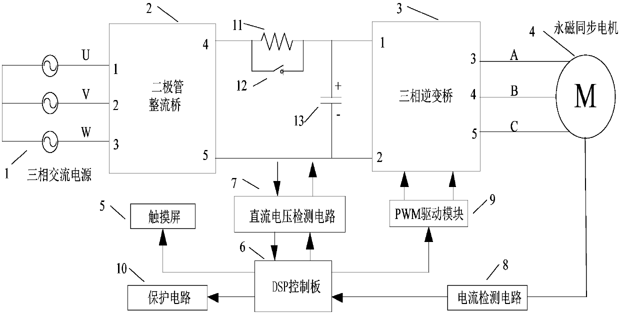
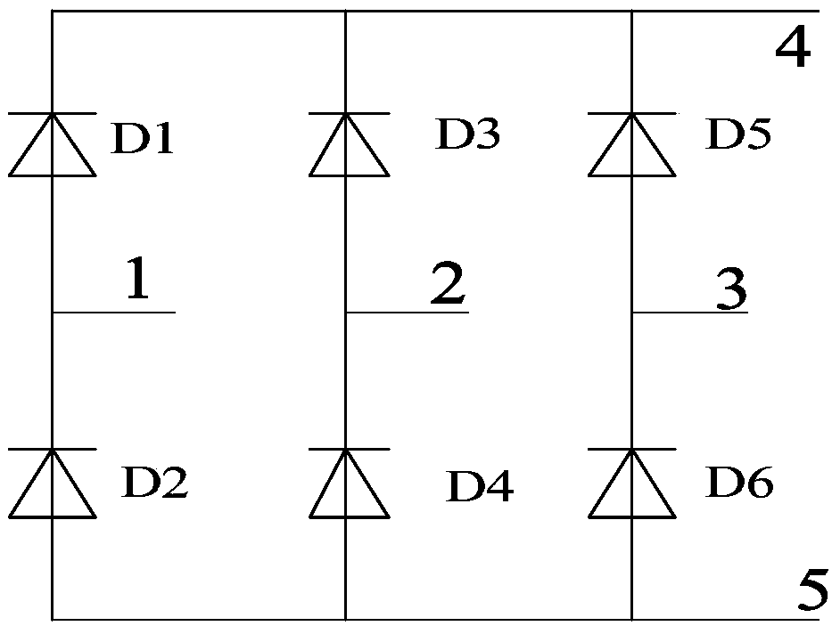
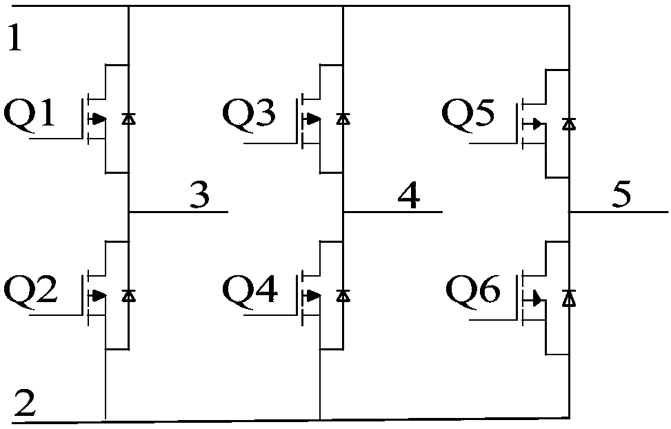
[0070] A control system for the rotor position angle of a permanent magnet synchronous motor, including a rectifier bridge 2 whose input end is connected to the UVW three phases of the three-phase alternating current 1, and a three-phase three-phase whose output end ABC three-phase is connected to the permanent magnet synchronous motor 4 correspondingly The inverter bridge 3, and the PWM drive module 9 and the DSP control board 9, and the DC voltage detection circuit 7 electrically connected to the control board to detect the output voltage of the rectifier bridge respectively, are used to detect the current detection of the stator current of the permanent magnet synchronous motor Circuit 8, and protection circuit 10, the input of the protection circuit 10 is connected to the output of the DC voltage detection circuit and the output of the current detection circuit, and the output of the protection circuit is connected to the control board and the PWM drive module respectively. ...

Embodiment 2

[0081] The DC voltage detection circuit 7 of the present invention is used to collect the output voltage of the rectifier, and it includes positive and negative input terminals and the first operational amplifier 14 of the voltage acquisition terminal, and the output of the first operational amplifier 14 is adjusted by the signal after the resistor R5 The unit is then connected to the signal processing module, and at the same time, the output of the first operational amplifier is connected to the input terminal through a resistor R4, and a capacitor C2 is connected in parallel to the resistor R4. At the same time, the positive input terminal of the first operational amplifier is grounded after passing through the capacitor C1, and meanwhile, a resistor R3 is also provided in parallel with the capacitor C1.

[0082] The current detection circuit is used to collect the stator current of the motor, and it includes a sensor arranged on the stator. The positive pole and the negative...

Embodiment 3

[0091] (1) The construction principle of the sliding mode observer

[0092] The voltage equation of PMSM in the α-β coordinate system can be expressed as:

[0093]

[0094] where i s is the stator current, i s =(i α ,i β ) T ;

[0095] u s is the stator voltage, u s =(u α ,u β ) T ;

[0096] E. s is the back electromotive force of the motor, E s =(E α ,E β ) T ;

[0097] A is the coefficient matrix, A=(-R s / L s )I;

[0098] B is the coefficient matrix, B=(1 / L s )I;

[0099] I is the identity matrix;

[0100] R s is the stator resistance;

[0101] L s is the stator inductance.

[0102] Since the electrical time constant of the PMSM is very small, the back EMF is regarded as the disturbance of the system, and the sliding mode observer equation obtained is as follows:

[0103]

[0104] In the formula is the stator current estimate,

[0105] K is K=k.I, where k is the sliding mode gain.

[0106] The current observation error equation of the ...


PUM


Abstract

The invention discloses a method for controlling a rotor position angle of a permanent magnet synchronous motor and a control method. The control method is to establish a sliding mode model and obtaina position angle estimation equation. By collecting the stator current signal of the permanent magnet synchronous motor, the rotor position can be calculated effectively, and the sensorless setting can be realized. Moreover, the current and the voltage are collected and input into the protection circuit, and additional protection is realized by using hardware, wherein a protection circuit 10 is electrically connected to a controller or a protection signal is directly input into a PWM driving module 9, and a PWM signal is enabled to be enabled under control. Once a fault signal occurs, the PWMsignal is directly blocked to implement the hardware protection function, and the direct driving mode is adopted to reduce the possibility of interruption due to the control panel fault interference.

Description

technical field [0001] The invention belongs to the technical field of motor control, and in particular relates to a control method and a control system for the rotor position angle of a permanent magnet synchronous motor. Background technique [0002] AC permanent magnet synchronous motor has been widely used in many fields such as industrial control and aerospace because of its high energy utilization rate and excellent mechanical properties. The permanent magnet synchronous motor usually adopts the vector control method, which needs to detect the rotor position angle at all times for calculation control. The rotor position angle is generally obtained by a mechanical position sensor, but the existence of the mechanical sensor increases the size and cost of the motor and reduces the The reliability of the system also limits its popularization and application in some special occasions. [0003] Moreover, the existing logic control mainly relies on software for protection, a...

Claims


Application Information

Patent Timeline
Patent Type & Authority Applications(China)
IPC IPC(8): H02P21/00H02P21/18H02P6/182
CPCH02P6/182H02P21/0007H02P21/18H02P2203/03
Inventor 魏振赵武玲赵楠彭树文高亚男姚广任祥正岳金磊张楠
Owner RES INST OF PHYSICAL & CHEM ENG OF NUCLEAR IND
Why Eureka
Try Eureka