Vertical type sinter cooler and sinter cooling method

A technology of cooler and sinter, which is applied in the field of iron making, and can solve the problems of material wear at the feed inlet, atmospheric particulate pollution, and uneconomical economic indicators.

Pending Publication Date: 2018-07-10
ZHONGYE-CHANGTIAN INT ENG CO LTD
View PDF7 Cites 4 Cited by
  • Summary
  • Abstract
  • Description
  • Claims
  • Application Information

AI Technical Summary

Problems solved by technology

No matter which way you choose, it will cause a high investment cost, which is not cost-effective in terms of economic indicators;
[0007] 2) The open circulation of the air flow leads to low utilization rate of waste heat and pollutes the environment: Since the air flow of the "extraction type longitudinal plate cooling technology" is an open circuit circulation, the air from the waste heat boiler is directly exhausted and not recycled, resulting in more than 100 Sensible heat of the air at a high temperature is wasted, and the discharged air contains a large amount of small particles of dust, causing a certain degree of particulate matter pollution to the atmosphere;
[0008] 3) The material at the feed inlet is severely worn: due to the "ventilated longitudinal plate cooling technology" that sets the material seal at the feed chute, there will be a friction distance between the lower part of the material seal and the upper layer of the material surface in the plate cooler box
At this time, the sintered material is easily pulverized and broken when it is rubbed under the double-layer harsh working conditions of high temperature and upper material column extrusion, thereby reducing the yield of the sintering machine;
[0009] 4) The environmental pollution is serious: due to the negative pressure ventilation technology adopted in the "ventilation type longitudinal plate cooling technology", it does

Method used


Image

  • Vertical type sinter cooler and sinter cooling method
  • Vertical type sinter cooler and sinter cooling method
  • Vertical type sinter cooler and sinter cooling method

Examples


Embodiment 1

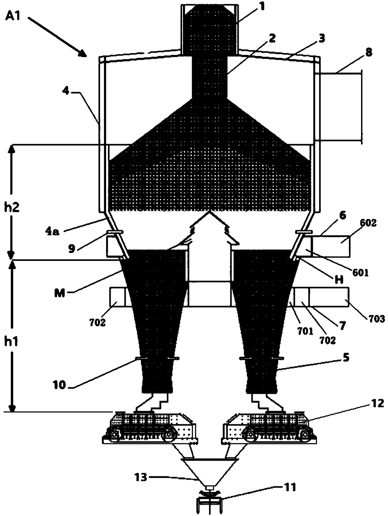
[0112] The height of the tower body consisting of the top cover and the tower wall is 9 meters, and the outer diameter of the tower body is 13 meters. The height of the discharge cone is 7 meters.

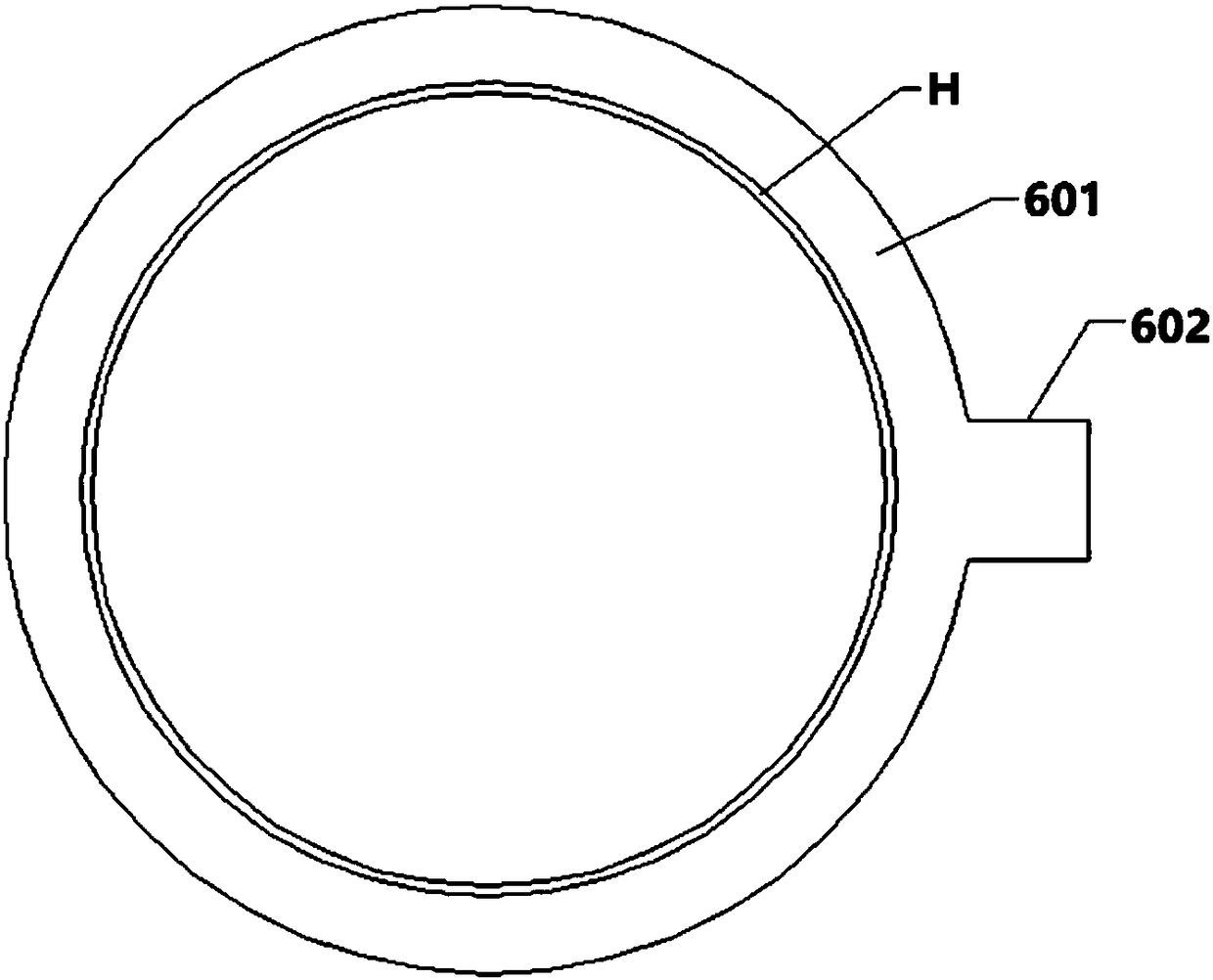
[0113] The diameter of the hood is 2.5 meters. The inner diameter of the wind ring is about 11 meters.

[0114] The daily processing capacity of sinter is 8600 tons / day. The temperature of the sintered ore before entering the silo is about 700°C, and the temperature of the hot air at the hot air outlet 8 reaches about 500°C. The recovered heat is used to generate electricity, and the power generation is about 34 kWh.

[0115] Compared with the prior art annular cooler, the advantages are: high power generation, low air leakage rate, small dust emission, simple and reliable equipment, and because of better sealing, the technology of the present invention can provide higher temperature hot air for generating High-temperature steam significantly improves power generation efficienc...


PUM


Abstract

The invention discloses a vertical type sinter cooler and a sinter cooling method. A plate type ore feeder unloading type vertical cooler comprises a material bin (1), a material distribution pipe (2), a tower, a plurality of discharge conical hoppers (5), an air ring (H), an air cap (M) and a hot air outlet (8). The tower comprises a tower top cover (3) and a tower wall (4). The discharge conicalhoppers (5) are located below the tower wall (4). The hot air outlet (8) is formed in the upper portion of the tower wall (4) or in the tower top cover (3). The top cover (3) is fixedly connected with the upper end of the tower wall (4). The material bin (1) is arranged above the top cover (3). The upper end of the material distribution pipe (2) is connected with the bottom of the material bin (1). The lower end of the material distribution pipe (2) stretches into the place below the top cover. The multiple discharge conical hoppers (5) are distributed annularly at the lower end of the towerwall (4) or are distributed evenly in the peripheral direction. A circle of fixed gap is formed between the lower portion of the tower wall and the tops of the multiple discharge conical hoppers (5) and serves as the air ring (H). The air cap (M) upwards stretching into the inner space of the tower is arranged in the bottom center of the tower, and a plate type ore feeder (12) is arranged below each discharge conical hopper (5).

Description

technical field [0001] The invention relates to a vertical sinter cooler and a sinter cooling method, belonging to the fields of ironmaking and environmental protection. Background technique [0002] In the modern sintering process, "cooling" is one of the most critical processes. After the sintered ore has been roasted by the sintering machine, it has formed a high-temperature finished ore. How can it be protectively cooled without affecting its quality and yield, so that it can be sent to the finished product ore bin through a belt conveyor, and at the same time The perfect recovery and utilization of the sensible heat energy it carries has always been a problem that technicians in the industry have been constantly studying. Since the 1960s, the cooling process of sinter has been developed rapidly, which is mainly divided into three categories: belt cooling, ring cooling and disk cooling. In the late market competition, the strip cooling technology was eliminated, and th...

Claims


Application Information

Patent Timeline
IPC IPC(8): F27D15/02F27D17/00
CPCF27D15/0286F27D17/004F27M2003/04F27D2017/006
Inventor 张震戴传德贺新华刘克俭
Owner ZHONGYE-CHANGTIAN INT ENG CO LTD
Why Eureka
Try Eureka