Hydraulic hybrid power system for road sweeper

A hybrid system and road cleaning technology, applied in hybrid vehicles, pneumatic power units, power units, etc., can solve the problems of limited fuel economy improvement, short driving mileage for cleaning work, immature and perfect technology, etc.

Inactive Publication Date: 2018-07-17
JILIN UNIV
View PDF15 Cites 6 Cited by
  • Summary
  • Abstract
  • Description
  • Claims
  • Application Information

AI Technical Summary

Problems solved by technology

Hybrid energy-saving technology has been promoted and applied to a certain extent in the field of road sweepers, but the existing technology is not mature enough.
For example, the Chinese patent publication number is CN102383388A, and the publication date is 2012-03-21, which discloses a hybrid drive system of a large-scale road sweeper. The system adopts a parallel hybrid configuration of an engine, a generator and a motor. The auxiliary engine improves fuel economy, but all its components are driven by motors, which consumes a lot of power and the electronic control system is complicated; another example is the Chinese patent No. CN204674365U, the publication date is 2015-09-30, which discloses a large oil Electric hybrid road sweeper power drive system, the system adopts the parallel hybrid configuration of the engine and the motor, although the auxiliary engine is canceled, but the motor cannot adjust the working range of the engine, the improvement of fuel economy is limited, and the battery energy cannot be timely Supplement, the driving range of cleaning work is short; another example is the Chinese patent No. CN104150838A, the publication date is 2015-12-16, which discloses a power drive system of a parallel hybrid electric washing and sweeping vehicle. The hybrid configuration, although the fuel consumption of the whole vehicle is reduced by canceling the auxiliary engine, but the system uses 6 clutches and 1 transfer case, the transmission efficiency from the engine to the working parts is very low, and the use of dual motors increases the cost and makes the whole vehicle Difficult to arrange

Method used


Image

  • Hydraulic hybrid power system for road sweeper
  • Hydraulic hybrid power system for road sweeper
  • Hydraulic hybrid power system for road sweeper

Examples


Embodiment Construction

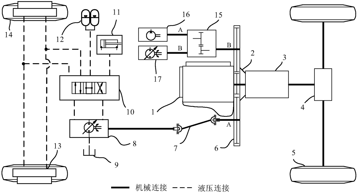
[0035] A hydraulic hybrid system for a road sweeper according to the present invention includes a mechanical transmission part and a hydraulic transmission part, and the mechanical transmission part includes an engine 1, a clutch 2, a gearbox 3, a drive axle 4, and a rear wheel 5 , power take-off 6, universal joint 7, front wheel 14, transfer case 15, fan device 16, high-pressure water pump device 17; the hydraulic transmission part includes hydraulic pump assembly 8, oil tank 9, hydraulic control valve group 10, cleaning Device control assembly 11 , accumulator assembly 12 , hydraulic motor assembly 13 .

[0036] Engine 1 is a four-stroke diesel generator, the output shaft of which is flanged or splined to the input shaft of clutch 2, and the output shaft of clutch 2 is connected to the input shaft of gearbox 3 by a spline pair or both are the same. shaft connection, the output shaft of the gearbox 3 is connected with the drive axle 4 by a universal joint, the drive axle 4 is...


PUM


Abstract

The invention discloses a hydraulic hybrid power system for a road sweeper to solve problems of poor fuel economy and emission performance, large noise, bad working environment, difficult chassis layout and high cost of manufacture and use. The hydraulic hybrid power system for the road sweeper comprises a mechanical drive part and a hydraulic drive part. A hydraulic pump, a fan and a high pressure water pump obtain power from an engine through a suction device; a valve group is controlled to switch to different working positions through a hydraulic pressure, and the transfer between a freewheel mode, a creeping driving mode, an accumulator driving power mode and a braking energy recovery mode of the hydraulic system is realized. The hydraulic hybrid power system for the road sweeper can not only meets various functional requirements of a sweeper, but also greatly improves fuel economy and emission of a traditional road sweeper. Noise is small, working environment is good, structures of hydraulic components are compact and price is moderate, thus difficulty of chassis layout is reduced and cost of use is reduced.

Description

technical field [0001] The invention relates to the field of road sweeping vehicles, in particular to a hydraulic hybrid power system for the road sweeping vehicle. Background technique [0002] As a kind of sanitation equipment, road sweeper is a new type of efficient cleaning equipment integrating road cleaning, garbage recycling and transportation. Traditional sweepers are mostly refitted on a special car chassis and equipped with two engines. During the transfer operation, the main engine works, and the auxiliary engine is idle; during the cleaning operation, the main and auxiliary engines work at the same time, the main engine is responsible for the movement of the vehicle, and the auxiliary engine drives the cleaning devices such as the sweeping plate, fan, and high-pressure water pump to work. The vehicle speed is low, the load rate of the main engine is very low, the fuel economy and emission are very poor, and the two engines work at the same time, the noise is ver...

Claims


Application Information

Patent Timeline
Patent Type & Authority Applications(China)
IPC IPC(8): B60K6/12B60K25/02E01H1/08E01H1/10
CPCB60K6/12B60K25/02B60K2025/026E01H1/08E01H1/101Y02T10/62Y02T10/92
Inventor 曾小华刘持林宋大凤李立鑫李文远李广含崔臣王星琦云千芮纪人桓
Owner JILIN UNIV
Why Eureka
Try Eureka