Automatic temperature control system and method for sample heat treatment process under ultrahigh vacuum
A technology of temperature control system and temperature control method, applied in the direction of temperature control, control/regulation system, electric controller, etc., which can solve the problems of insufficient response speed of artificial temperature regulation and inaccurate control, etc., to improve efficiency and accuracy , the effect of accurate temperature control
- Summary
- Abstract
- Description
- Claims
- Application Information
AI Technical Summary
Problems solved by technology
Method used
Image
Examples
Embodiment 1
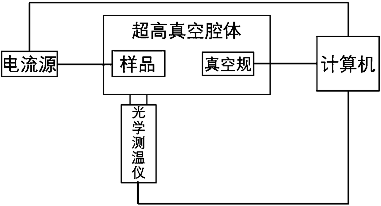
[0043] like figure 1 As shown, an automatic temperature control system for the sample heat treatment process under ultra-high vacuum, including an optical thermometer and a vacuum gauge, and also includes a computer and a current source. The vacuum gauge is located in the ultra-high vacuum sample heating device, and the optical gauge The thermometer is installed outside the sample observation window of the ultra-high vacuum cavity, the optical thermometer and the vacuum gauge are connected to the computer, the computer is connected to the current source, and the current source is connected to the sample; wherein, the computer reads the optical thermometer through the RS232 serial port module. Readings from thermometers and vacuum gauges.
[0044] The computer collects the temperature and vacuum degree of the optical thermometer and the vacuum gauge sample, compares it with the set temperature, calculates the required heating current through the PID algorithm, controls the outp...
Embodiment 2
[0047] like figure 1 As shown, the automatic temperature control system of an ultra-high vacuum sample heat treatment process in this embodiment is further improved on the basis of Embodiment 1, and the vacuum gauge described is an Agilent UHV24P ionization vacuum gauge. With high measurement accuracy and fast response speed, it can accurately and quickly feedback the actual vacuum degree and heat treatment quality of the environment where the sample is located.
[0048] The optical thermometer is the PhotriX infrared thermometer of LumaSense Company. The measurement accuracy is high (0.01°C), the range is wide (135°C-2400°C), and the response speed is fast (1ms), which can accurately feedback the actual temperature of the sample.
[0049] The current source is Puyuan Precision Electronics DP811A programmable current source. The output current value has high accuracy (0.5mA) and rapid response (50μs), which can accurately and quickly control the actual heating power, rate an...
Embodiment 3
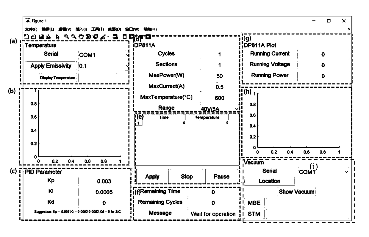
[0051] like figure 2 As shown, the automatic temperature control system of a kind of ultra-high vacuum sample heat treatment process of the present embodiment is further improved on the basis of embodiments 1 and 2, Matlab software is installed on the computer, and PID is constructed in Matlab software controller. Build a graphical control module in Matlab software, and the graphical control module includes an optical thermometer operation module, a sample temperature display module, a PID parameter module, a current source heating parameter setting module, a sample temperature preset module, and a heat treatment process module, current source display module, heating process display module and vacuum display module.
[0052] It has the following advantages: 1) Automatically control the sample temperature heating process to avoid repetitive labor consumption; 2) According to different samples and heat treatment process requirements, set various parameters in the heat treatmen...
PUM
 Abstract
Description
Claims
Application Information
 - R&D
- Intellectual Property
- Life Sciences
- Materials
- Tech Scout
- Unparalleled Data Quality
- Higher Quality Content
- 60% Fewer Hallucinations
Browse by: Latest US Patents, China's latest patents, Technical Efficacy Thesaurus, Application Domain, Technology Topic, Popular Technical Reports.
© 2025 PatSnap. All rights reserved.Legal|Privacy policy|Modern Slavery Act Transparency Statement|Sitemap|About US| Contact US: help@patsnap.com


