Treatment technology for photocatalytically degrading dyestuff wastewater
A technology of dye wastewater and treatment process, which is applied in the direction of special compound water treatment, light water/sewage treatment, water/sewage treatment, etc., to achieve the effect of simple operation, improved activity, and improved photocatalytic degradation activity
- Summary
- Abstract
- Description
- Claims
- Application Information
AI Technical Summary
Problems solved by technology
Method used
Image
Examples
Embodiment 1
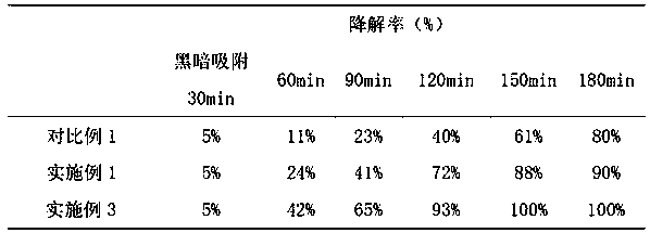
[0031] Example 1 Preparation of perovskite-wrapped hydrotalcite-like substrate
[0032] Specifically include the following steps:
[0033] a. Prepare Mg(NO 3 ) 2 and Al(NO3 ) 3 A mixed aqueous solution, wherein the mol ratio of Mg to Al is: 3, wherein the concentration of the mixed aqueous solution is 0.4mol / L;
[0034] b. Under the stirring condition of 150-300 rpm / min, to Na 2 CO 3 Add the mixed aqueous solution prepared in step a dropwise to the aqueous solution, and drop it for 1 hour. During the dropwise addition, Na 2 CO 3 The volume ratio of the aqueous solution and the mixed aqueous solution prepared in step a is 1:4, and after the dropwise addition is completed, use Na 2 CO 3 Adjust the pH value of the system to 10 with the aqueous solution, and maintain the aging at 80°C for 12 hours;
[0035] c. Suction filter the precipitate prepared in step b, wash it with deionized water, and then dry it at 100°C for 6h, then calcinate it in an air atmosphere at 800°C fo...
Embodiment 2
[0038] The preparation of embodiment 2 ionic liquid
[0039] Dissolve 3-bromopropylamine hydrobromide in anhydrous acetonitrile, add 1-methylimidazole, heat up to 55°C for reaction, the time from the start of temperature rise to the end of the reaction is 24h, remove the solvent, and use methanol with a volume ratio of 1:1 Wash with a mixed solution of diethyl ether, remove methanol and diethyl ether by rotary evaporation, dissolve the residue in methanol, add saturated NaOH methanol solution dropwise until the pH value of the solution reaches 8.5, remove methanol by rotary evaporation, and centrifuge to separate inorganic salts from hexafluoro Ammonium phosphate was reacted for 1 h, and the orange-red 1-methyl-3 aminopropylimidazolium hexafluorophosphate ionic liquid was obtained by silica gel column chromatography, which was stored at 4°C for later use. Wherein, the molar ratio of 3-bromopropylamine hydrobromide, 1-methylimidazole, and ammonium hexafluorophosphate is 4:1:3. ...
Embodiment 3
[0040] Example 3 Ionic liquid-modified perovskite-coated hydrotalcite-like photocatalyst
[0041] f. In an ice bath and nitrogen atmosphere, take a certain amount of methanol solution of orange-red 1-methyl-3 aminopropylimidazolium hexafluorophosphate ionic liquid, then add perovskite-coated hydrotalcite-like substrate to it, and stir the reaction 2h. The solvent was removed by rotary evaporation of the reaction product to obtain a light yellow powder, which is a perovskite-coated hydrotalcite-like catalyst modified by ionic liquids. The mass ratio of 1-methyl-3 aminopropylimidazolium hexafluorophosphate ionic liquid to perovskite-wrapped hydrotalcite substrate is 1:25.
PUM
 Abstract
Description
Claims
Application Information
 - R&D
- Intellectual Property
- Life Sciences
- Materials
- Tech Scout
- Unparalleled Data Quality
- Higher Quality Content
- 60% Fewer Hallucinations
Browse by: Latest US Patents, China's latest patents, Technical Efficacy Thesaurus, Application Domain, Technology Topic, Popular Technical Reports.
© 2025 PatSnap. All rights reserved.Legal|Privacy policy|Modern Slavery Act Transparency Statement|Sitemap|About US| Contact US: help@patsnap.com

