Intelligent processing terminal cooling device

A technology of intelligent processing and cooling device, applied in cooling/ventilation/heating renovation, coating, electrical equipment structural parts, etc., can solve the problems of reduced life, damage, high energy consumption, etc., to achieve good compatibility of base materials, Enhance mechanical strength and increase the effect of high temperature resistance

Inactive Publication Date: 2018-09-04
NANYANG MEDICAL COLLEGE
View PDF10 Cites 1 Cited by
  • Summary
  • Abstract
  • Description
  • Claims
  • Application Information

AI Technical Summary

Problems solved by technology

[0002] With the continuous development of science and technology, intelligent processing equipment is becoming more and more popular. For these intelligent processing equipment, due to the increasingly advanced manufacturing process and faster processing speed, the problem of heat generation has not been well avoided. It is the culprit that affects the life and speed of the intelligent processing terminal. The conventional processing methods are to improve the process and reduce the power, to install a large cooling fin on the heating element, and to install a high-power fan on the cooling fin. The method is to increase air convection, which increases the enrichment of dust invisibly. Over time, it will inevitably cause dust to block the cooling fin and enter some important components, which will cause dust to enter the interior, damage the components, and lead to processing speed. Decrease and greatly reduce the service life, and may even cause the components to burn out due to the inability to dissipate heat in time due to the accumulation of dust;
Due to the high energy consumption of semiconductor cooling chips, the heat dissipation effect is not good for high-load computing equipment, and it is not eye-catching enough, and it is easy to be kicked down and cause damage

Method used


Image

  • Intelligent processing terminal cooling device
  • Intelligent processing terminal cooling device
  • Intelligent processing terminal cooling device

Examples


Embodiment 1

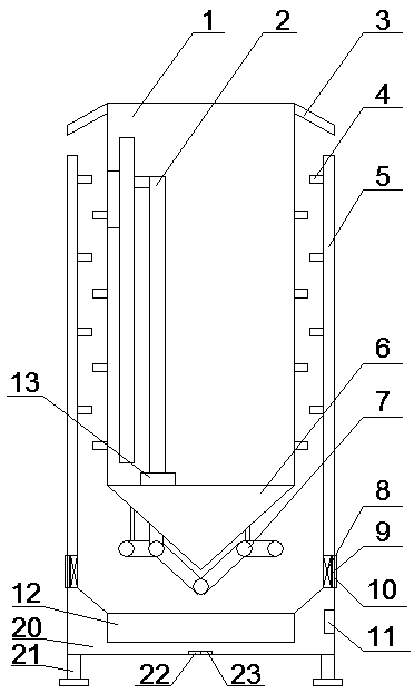
[0045] An intelligent processing terminal cooling device, comprising a box body 1, an internal circulation mechanism arranged inside the box body 1 to cooperate with heating elements, an outer circulation mechanism arranged at the lower part of the box body, and an outer circulation mechanism arranged in the outer circulation mechanism The lower coolant generator, the return mechanism arranged on the side of the box, and the controller 11 arranged on the side wall of the box and matched with the coolant generator and the internal circulation mechanism;

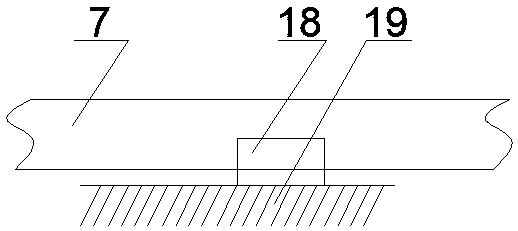
[0046] The internal circulation mechanism includes an internal circulation pipe 7 arranged inside the box and in contact with the heating element for heat conduction, and the internal circulation pipe 7 is provided with a micro oil pump 13 connected to the controller 11;

[0047] The external circulation mechanism includes an external serpentine pipe 7 arranged at the lower part of the box body 1 and provided through a bracket ...

Embodiment 2

[0063] It differs from Embodiment 1 in that:

[0064] The bottom of the box body 1 is a conical bottom surface 6a.

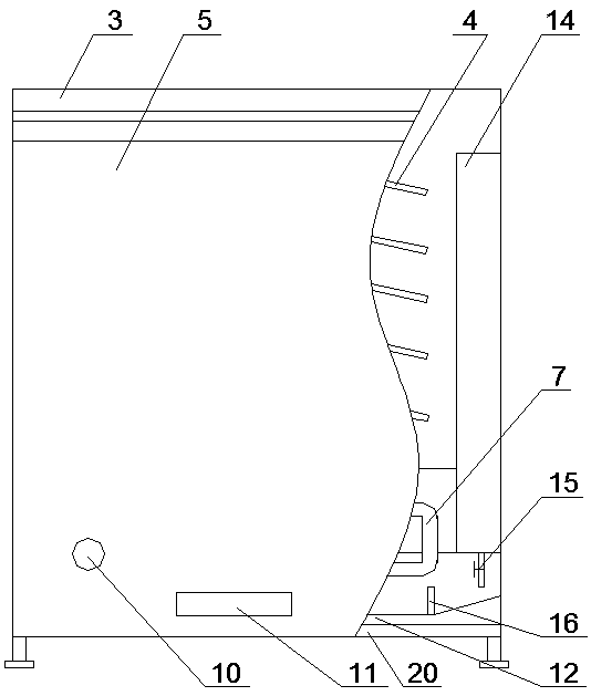
[0065] The condensation plate 4 is a circular arc plate 4a arranged on the return plate 5 or the peripheral wall of the box body 1 .

[0066] The box 1 is a cylinder.

[0067] The bottom of the base 20 is provided with a plurality of telescopic rods 21 for support, and a balance detection module that cooperates with the telescopic rods 21 and is arranged at the center of the bottom of the base 20;

[0068] Described balance detection module comprises MEMS gyroscope 22 and MEMS accelerometer 23;

[0069] The telescopic rod 21 is an electric telescopic rod, and the end of the electric telescopic rod is provided with feet.

[0070] The surface of the outer serpentine tube 7 is provided with fins for heat dissipation.

[0071] A solenoid valve 15 is provided at the outlet of the lower part of the water tank 1, and the solenoid valve 15 is connected to the water ...

Embodiment 3

[0078] It differs from Embodiment 2 in that the fluorescent paint is mainly made of the following raw materials in parts by weight:

[0079] 34 parts of acrylic emulsion, 26 parts of alkyd resin, 5 parts of fluorescent powder, 3 parts of glass beads, 1.6 parts of glass fiber, 10 parts of titanium dioxide, 7 parts of ultrafine barium sulfate, 9 parts of ethanol, 8 parts of water and 1.4 parts of dispersant share.

[0080] Wherein the preparation method of fluorescent powder comprises the following steps: dissolving strontium chloride and aluminum chloride in a sufficient volume fraction of 60% ethanol solution, then adding silicon nitride and europium trioxide to disperse evenly to form a suspension, and then using Ammonia water adjusts the pH value to 8-9, obtains a precipitate after vacuum filtration, vacuum-dries at 70°C for 3 hours, and calcines at 1050°C for 2 hours under a CO reducing atmosphere to obtain fluorescent powder. The strontium chloride, aluminum chloride, nitr...


PUM

PropertyMeasurementUnit
diameteraaaaaaaaaa
lengthaaaaaaaaaa
particle size (mesh)aaaaaaaaaa

Abstract

The invention belongs to the technical field of intelligent processing terminal cooling and specifically provides an intelligent processing terminal cooling device. The device comprises a box body, aninternal circulation mechanism arranged in the box body and matched with a heating element of an intelligent processing terminal, an external circulation mechanism arranged under the box body, a coolant generator arranged under the external circulation mechanism, a backflow mechanism arranged on the side surface of the box body, a controller arranged on the side wall of the box body and cooperated with the coolant generator and the internal circulation mechanism, and a fluorescent paint sprayed onto the outer wall of the box body. For the problems that the device cannot be suitable for large-scale intelligent processing equipment, is poor in heat radiation effect and poor in dustproof effect and easy to be kicked since the device is not striking enough in the prior art, the box body is sealed wholly, and cooling fins and excessive space are reduced, so that the box body is allowed to become more compact and small, and is striking, and the phenomenon of damage due to kick is prevented.

Description

technical field [0001] The invention relates to the technical field of intelligent processing terminal cooling, in particular to an intelligent processing terminal cooling device. Background technique [0002] With the continuous development of science and technology, intelligent processing equipment is becoming more and more popular. For these intelligent processing equipment, due to the increasingly advanced manufacturing process and faster processing speed, the problem of heat generation has not been well avoided. It is the culprit that affects the life and speed of the intelligent processing terminal. The conventional processing methods are to improve the process and reduce the power, to install a large cooling fin on the heating element, and to install a high-power fan on the cooling fin. The method is to increase air convection, which increases the enrichment of dust invisibly. Over time, it will inevitably cause dust to block the cooling fin and enter some important c...

Claims


Application Information

Patent Timeline
Patent Type & Authority Applications(China)
IPC IPC(8): H05K7/20H05K5/02C09D133/00C09D167/08C09D7/61
CPCH05K7/20272C08K2003/2241C09D7/61C09D7/70C09D133/00C09D167/08H05K5/0217H05K7/20345H05K7/20381C08L67/08C08K13/04C08K7/14C08K7/20C08K3/22
Inventor 王秋红
Owner NANYANG MEDICAL COLLEGE
Why Eureka
Try Eureka