Batch preparation method of hfcvd for diamond-coated tools with complex shapes

A complex shape, diamond film technology, applied in metal material coating process, coating, gaseous chemical plating and other directions, can solve the difficulty, affect the appearance quality of complex shape diamond film coating tools, and the temperature field distribution on the surface of the tool substrate is not enough. Uniformity and other issues to achieve the effect of ensuring uniform deposition

Active Publication Date: 2019-11-01
SHANGHAI JIAO TONG UNIV
View PDF2 Cites 0 Cited by
  • Summary
  • Abstract
  • Description
  • Claims
  • Application Information

AI Technical Summary

Problems solved by technology

In particular, most drill bits and milling cutters have slender shafts and poor heat conduction, which makes the above-mentioned control objectives more difficult
[0007] In addition, for slender and complex-shaped cutting tools, under the premise that the cutting edge position meets the requirements of high-quality diamond film deposition, the temperature at the shank and the concentration of reactive groups are often favorable for non-diamond impurity components such as amorphous carbon and graphite. The growth of the "black rod" is very easy to appear, which affects the appearance quality of the complex shape diamond film coating tool
[0008] After searching the literature of the prior art, it was found that Chinese Patent Application No. 200310108306.0 reported a "device for preparing a diamond coating on an integral carbide rotary tool", which disclosed a rotary shaft that can drive a tool to rotate The monolithic carbide tool diamond coating device, but the special deposition device specially made by the above technology is only an experimental equipment for a single monolithic carbide tool diamond coating with complex shapes, and is not suitable as a CVD diamond-coated complex shape cemented carbide tool. Batch preparation device
Chinese Patent Application No. 201110028846.2 provides a batch preparation method of hot wire chemical vapor deposition of diamond-coated tools with complex shapes, which adopts the arrangement of upper and lower rows of hot wires. During the CVD diamond coating deposition process, the tool is installed on a sandwich base, but the above The technical hot wire arrangement is complicated, the temperature field distribution on the surface of the tool substrate is not uniform enough, and the cooling effect of the tool needs to be improved

Method used


Image

  • Batch preparation method of hfcvd for diamond-coated tools with complex shapes
  • Batch preparation method of hfcvd for diamond-coated tools with complex shapes
  • Batch preparation method of hfcvd for diamond-coated tools with complex shapes

Examples


Embodiment 1

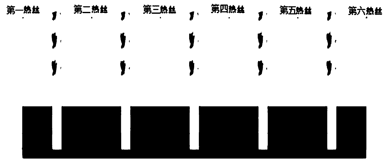
[0038] Such as figure 1 As shown, a CVD diamond coating is coated on a milling cutter for machining graphite, and the diameter of the shank is The blade length is 30mm, and the overall length of the tool is 100mm. The structure of the tool cooling base used in this embodiment is as follows: the size of red copper is 20×60×120 mm in height, width and length, the size of stainless steel is 30×60×120 mm in height, width and length, and the thickness is 0.4 mm. 60×120mm, 40 drills are evenly spaced on the tool cooling base hole (hole depth 40mm), in order to install and insert 40 milling cutters upright. The molybdenum sheet covers the copper layer and the stainless steel layer. In the present invention, the role of the molybdenum sheet is to prevent the reaction group from reaching the lower tool handle through its precise inner surface of the drilled hole and closely cooperate with the tool handle to prevent the "black rod" phenomenon; in addition, the molybdenum sheet has ...

Embodiment 2

[0061] The present embodiment is the same as embodiment 1, the difference is:

[0062] The tool cooling base used has a 3-layer structure: molybdenum sheet + graphite + stainless steel; the third step, single-layer diamond film deposition: after the reaction chamber is evacuated, the reaction gas (hydrogen and acetone) is introduced, and the single-layer diamond film is started after adjusting the pressure of the reaction chamber For the deposition of CVD diamond coating, the process parameters are: pressure 25 Torr, total gas flow rate 1000 ml / min, acetone / hydrogen (volume ratio) 2.6%, tantalum wire temperature about 2100 ° C, after 3 hours of deposition, the deposition on the blade A diamond coating about 6-8 microns thick was obtained. Rotate the position of each tool 5 by 90 degrees, and use the same process parameters for another 3 hours of deposition to obtain a diamond coating with a thickness of about 12-16 microns, which can effectively ensure the uniformity of the co...

Embodiment 3

[0064] The present embodiment is the same as embodiment 1, the difference is:

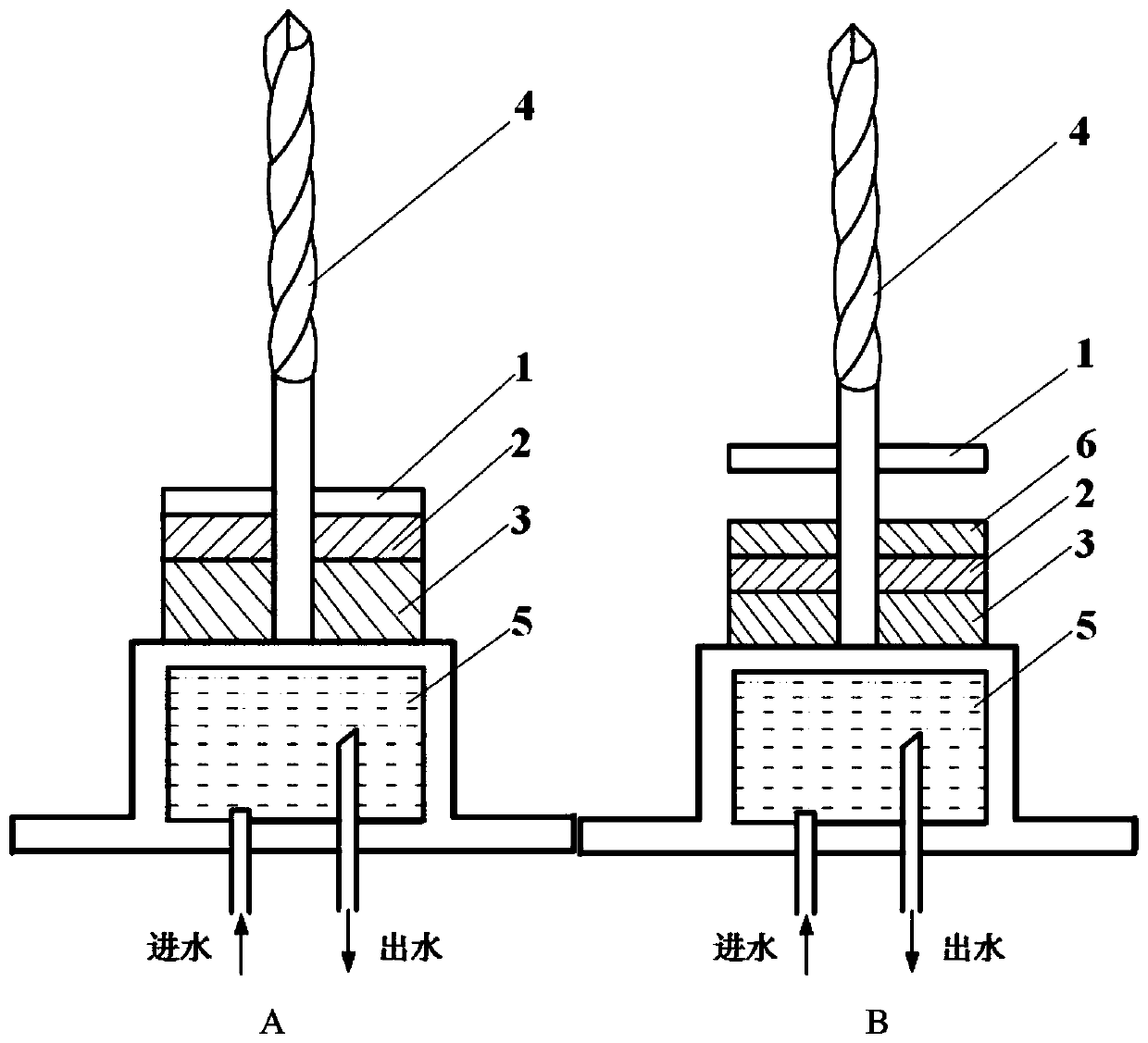
[0065] This embodiment adopts image 3 In the 4-layer tool cooling base shown in B, the uppermost molybdenum sheet layer 1 and the lower cooling base (graphite layer 6 + copper layer 2 + stainless steel layer 3) form a certain hollow space, and the graphite size is high, wide, The length is 15×60×120mm, the size of red copper is 10×60×120mm in height, width and length, the height, width and length of stainless steel are 20×60×120mm, and the molybdenum sheet 1 with a thickness of 0.4mm is cut into 60×120mm. Drill 40 evenly spaced holes in the tool cooling base hole (hole depth 40mm), in order to install and insert 40 milling cutters upright.

[0066] Using the same deposition parameters as in Example 1, a 10-12 micron thick micron-nano composite diamond film coating is finally obtained, and the coating uniformity can be effectively ensured. The milling cutter is used for graphite processing, and...


PUM

PropertyMeasurementUnit
thicknessaaaaaaaaaa
thicknessaaaaaaaaaa
thicknessaaaaaaaaaa

Abstract

The invention discloses an HFCVD batch preparation method of a complex-shaped diamond film coated cutter. A handle of the complex-shaped cutter after being pretreated is inserted into a cutter coolingbase to be placed on the water-cooled workbench of HFCVD equipment. The cutter cooling base is formed by optimally matching a molybdenum sheet layer, a graphitic layer, a red copper layer or a stainless steel layer, and a drill hole matched with the handle in diameter and length is formed in the cutter cooling base. The HFCVD equipment adopts a single-layer hot filament. In the cutter mounting and film growing processes, the HFCVD equipment can realize free lifting of the cutter cooling base by controlling the lifting of the water-cooled workbench. Hydrogen, a carbon source and a doped sourceenter into the surface of the complex-shaped cutter to deposit a single-layer or composite diamond film. The HFCVD batch preparation method can conveniently and effectively control the temperature value of the blade area of the cutter, ensures the uniform distribution of a temperature field and a density field of a reactive group, ensures the uniform deposition of the diamond film, and avoids ofdepositing carbon impurities on the handle position to cause the phenomenon of a black bar.

Description

technical field [0001] The invention relates to a method in the technical field of mechanical processing, in particular to a HFCVD batch preparation method for complex-shaped diamond film-coated tools. Background technique [0002] With the development of workpiece materials in the direction of lightweight and composite, high-silicon aluminum (lead) alloys, metal (ceramic) matrix composites, ceramics, carbon and graphite composites, other fiber-reinforced composites, laminate flooring and other difficult-to-process materials Used extensively in industries such as automotive, aerospace and tooling. Integral rotary tools mainly made of cemented carbide materials, such as twist drills, end mills and other complex-shaped tools, are widely used, and these tools wear seriously when processing the above-mentioned difficult-to-machine materials at high speeds, and the machining accuracy and surface quality Difficult to guarantee. [0003] Chemical vapor deposition (Chemical Vapor ...

Claims


Application Information

Patent Timeline
Patent Type & Authority Patents(China)
IPC IPC(8): C23C16/27C23C16/46
CPCC23C16/271C23C16/278C23C16/463
Inventor 孙方宏王新昶王华
Owner SHANGHAI JIAO TONG UNIV
Why Eureka
Try Eureka