An industrial flue gas scr denitration treatment system

A technology of industrial flue gas and treatment system, which is applied in the direction of gas treatment, separation method, dispersed particle separation, etc., can solve the problems of increasing particle deposition, increasing construction cost and operating cost, reducing mixer turbulence, etc.

Active Publication Date: 2020-12-15
江苏蓝电环保股份有限公司
View PDF5 Cites 0 Cited by
  • Summary
  • Abstract
  • Description
  • Claims
  • Application Information

AI Technical Summary

Problems solved by technology

Increasing the cross-sectional area of ​​the device not only causes the flow field in the tower to present a laminar flow state, reduces the turbulence of the mixer, and reduces the denitrification efficiency, but also increases the deposition of particulate matter in the flue gas, causing a large amount of dust to accumulate on the surface of the catalyst. It affects the activity of the catalyst and increases the escape of ammonia; increasing the height or length of the tower body greatly increases the amount of catalyst used, increasing construction and operating costs
[0004] There are also some technical solutions for SCR denitrification in the prior art. For example, a Chinese patent with application number 201510768338.6 discloses a double-spin SCR denitrification method and its device, including the denitrification tower body and the interior along the denitrification tower body. The first plate-type catalyst layer arranged on the circumferential surface is provided with a second plate-type catalyst layer in the first plate-type catalyst layer; the cavity between the first plate-type catalyst layer and the second plate-type catalyst layer is the first swirl catalytic reaction chamber, The cavity in the second plate catalyst layer is the second swirl catalytic reaction chamber; the bottom end of the second swirl catalytic reaction chamber is provided with a cyclone; the top of the first swirl catalytic reaction chamber is sealed and sealed in the denitration tower The upper side wall of the body is provided with a flue gas inlet pipe along the tangential direction of the inner circumference of the denitrification tower body; a plurality of swirl pipes are respectively arranged along the inner peripheral surface of the flue gas inlet pipe and the inner peripheral surface of the top of the first swirl catalytic reaction chamber. flow atomization nozzle; this technical solution can achieve high-efficiency denitrification, and the technical means are simple and easy to implement. Compared with the existing technology, not only the structure of the denitrification tower is simple and the cost is low, the cost of denitrification is greatly reduced, and the economic benefit is significantly improved; but in this solution The spiral airflow generated by the swirl atomizing nozzle and the cyclone will gradually weaken, and the mixing degree of the ammonia gas and the flue gas will also gradually weaken accordingly, thus affecting the inconsistent mixing ratio of the ammonia gas and the flue gas, and ultimately affecting the denitrification reaction. Effect

Method used


Image

  • An industrial flue gas scr denitration treatment system
  • An industrial flue gas scr denitration treatment system
  • An industrial flue gas scr denitration treatment system

Examples


Embodiment approach

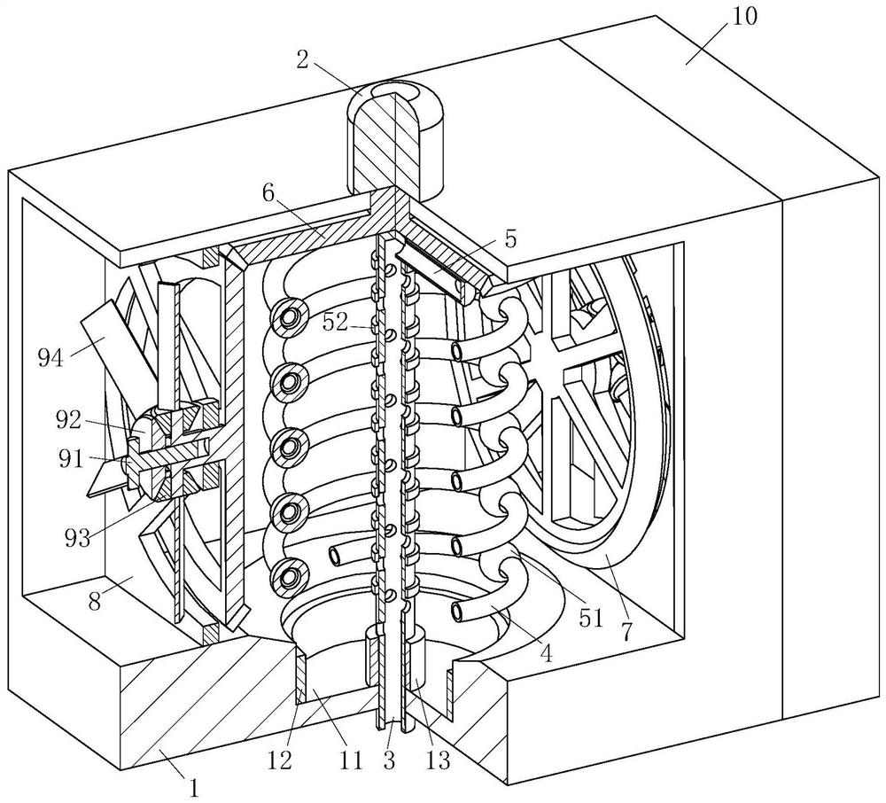
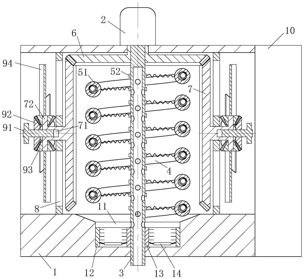
[0025] As an embodiment of the present invention, a cylindrical groove 11 is provided on the top of the bottom plate of the mixing chamber 1 below the counterweight 51; Brush plate 12; the No. 1 brush plate 12 is annular, and the inside of No. 1 brush plate 12 is provided with bristles; The cylindrical surface of the other end of the rotating tube 3 is provided with No. 2 brush plate 13; No. two brush plate 13 is annular, and No. two brush plate 13 outsides are provided with bristles; Described No. two brush plate 13 and No. one brush plate 12 are provided with vibrating plate 14; Described vibrating plate 14 is circular Ring shape, the inner side of the vibrating plate 14 is connected to the bottom of the No. 2 brush plate 13 through a set of springs, and the outer side of the vibrating plate 14 is connected to the bottom of the No. 1 brush plate 12 through a set of springs; when working, the speed of the motor 2 increases gradually At this time, the counterweight 51 drives t...


PUM


Abstract

The invention belongs to the technical field of industrial waste gas treatment, and particularly relates to an industrial smoke SCR denitration treatment system. The system comprises a mixing cavity,a motor, a rotating pipe, a spiral pipe and a connecting pipe, wherein the end head of a motor shaft is fixedly connected with one end of the rotating pipe; air outlets are formed in the cylinder surface of the rotating pipe; the cylinder surface of one end of the rotating pipe is fixedly connected with one end of the connecting pipe; the other end of the connecting pipe is fixedly connected withone end of the spiral pipe; air outlets are formed in the spiral pipe. According to the system, through rotation of the spiral pipe, ammonia gas is evenly released into the mixing cavity, and then theammonia gas and smoke of the mixing cavity are evenly mixed; through a driving gear, a driven gear is driven to rotate, so that the higher rotation speed of the motor is achieved, the higher concentration of the ammonia gas in the mixing cavity is achieved, and the concentration of the smoke which enters the mixing cavity corresponds to that of the ammonia gas, and then the optimal mixing ratio of the smoke to the ammonia gas is ensured.

Description

technical field [0001] The invention belongs to the technical field of industrial waste gas treatment, in particular to an industrial flue gas SCR denitrification treatment system. Background technique [0002] Traditional denitrification mainly uses selective catalytic reduction (SCR) and selective non-catalytic reduction (SNCR). Among them, the widely used SCR technology is an effective method to control NOx emissions from the tail gas. The reducing agents include urea, ammonia water and pure ammonia. Usually, NH3 is used as the reducing agent to reduce NOx to harmless NOx under the action of the catalyst. N2, thereby removing NOx in the flue gas. Reasonable selection and use of catalyst is the core of SCR technology. The structure of the catalyst mainly has three types: honeycomb type, flat plate type and corrugated plate type. Among them, flat or corrugated plate catalysts have better anti-dust and clogging capabilities than honeycomb catalysts, but the gas-solid cont...

Claims


Application Information

Patent Timeline
Patent Type & Authority Patents(China)
IPC IPC(8): B01D53/56B01D53/90
CPCB01D53/8631B01D53/90B01D2251/2062B01D2257/404B01D2258/0283
Inventor 王鹏
Owner 江苏蓝电环保股份有限公司
Why Eureka
Try Eureka