
Solar cell back electrode, solar cell and preparation method of solar cell back electrode

A technology for solar cells and back electrodes, applied in the field of solar cells, can solve the problems of holes, cracks, and large introductions in the film layer, and achieve the effects of improving high temperature tolerance, reducing residual stress, and good high temperature tolerance.

Active Publication Date: 2018-11-02
CHNA ENERGY INVESTMENT CORP LTD +1
View PDF6 Cites 2 Cited by
  • Summary
  • Abstract
  • Description
  • Claims
  • Application Information

AI Technical Summary

Problems solved by technology

[0007] After in-depth research, the inventors of the present invention found that although the double-layer back electrode structure of "high air pressure / low air pressure" in the prior art can effectively solve the problems of film adhesion and conductivity, the double-layer structure has low The air pressure film is thicker (thickness > 300nm), which usually introduces a large residual stress into the film. At the same time, in the high temperature environment where the absorbing layer is plated, because the thermal expansion coefficient of the glass is greater than that of the molybdenum back electrode layer, the molybdenum film The layer will be subjected to thermal stress, that is, the film layer is subjected to a large extrusion force of the glass substrate, and the dense film layer cannot release the extrusion force, resulting in defects such as holes or cracks in the film layer

Method used


Image

  • Solar cell back electrode, solar cell and preparation method of solar cell back electrode
  • Solar cell back electrode, solar cell and preparation method of solar cell back electrode
  • Solar cell back electrode, solar cell and preparation method of solar cell back electrode

Examples


preparation example Construction

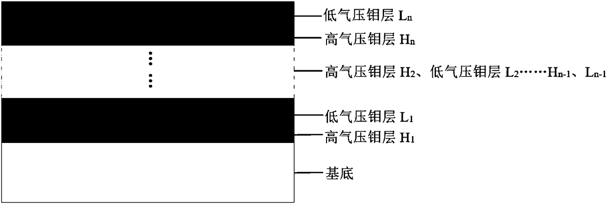
[0028] The preparation method of the back electrode of the solar cell provided by the present invention comprises adopting the magnetron sputtering method to sequentially and alternately deposit high-pressure molybdenum layers and low-pressure molybdenum layers on one side of the substrate as the bottom electrode, and the thickness of each high-pressure molybdenum layer is Each independently is 30-200nm, preferably each independently is 40-150nm, more preferably each independently is 50-100nm, the thickness of each low-pressure molybdenum layer is each independently 40-300nm, preferably each independently is 50-250nm , more preferably each independently is 100-200nm, the pressure of depositing each high pressure molybdenum layer is each independently 0.7-3.0Pa, preferably each independently is 1.0-2.5Pa, more preferably each independently is 1.0-2.0Pa, deposits The pressure of each low-pressure molybdenum layer is independently 0.01-0.5Pa, preferably independently 0.05-0.4Pa, m...

specific Embodiment approach

[0034] According to a specific embodiment of the present invention, the preparation method of the back electrode of the solar cell further includes, after the deposition of the high-pressure molybdenum layer and the low-pressure molybdenum layer, using the magnetron sputtering method on the outermost low-pressure molybdenum layer A surface molybdenum layer is deposited on the surface, and the pressure for depositing the surface molybdenum layer is 0.01-3.0Pa, preferably 0.05-1.5Pa, more preferably 0.1-1.0Pa. The specific structure of the solar battery back electrode formed in this way is high pressure molybdenum layer / low pressure molybdenum layer / ... / high pressure molybdenum layer / low pressure molybdenum layer / surface molybdenum layer. The thickness of the molybdenum layer on the surface is preferably 10-200 nm, more preferably 10-100 nm, further preferably 20-75 nm. The deposition rate of the molybdenum layer on the surface may be 5-30 nm / min, preferably 10-20 nm / min.

Embodiment approach

[0035] According to the present invention, in order to improve the adhesion of the bottom electrode on the surface of the substrate, preferably, the preparation method of the back electrode of the solar cell further includes, before depositing the high-pressure molybdenum layer and the low-pressure molybdenum layer, the surface of the substrate is first Pretreatment, the method of pretreatment includes cleaning the surface of the substrate, then putting it into a coating chamber to evacuate to below 5.0E-3Pa, and then baking at 100-200°C to remove water vapor. Wherein, the cleaning method may be, for example, at least one of alkali washing, alcohol washing, water washing and the like. According to a preferred embodiment of the present invention, the cleaning method includes ultrasonically cleaning the substrate in an alkaline cleaning solution for 10-30 minutes, taking out the substrate and rinsing it with deionized water to remove residual lye, and then Place the substrate in...


PUM


Abstract

The invention provides the field of a solar cell, and particularly discloses a solar cell back electrode, a solar cell and a preparation method of the solar cell back electrode. The preparation methodof the solar cell back electrode comprises the step of sequentially and alternatively depositing high-atmospheric pressure molybdenum layers and low-atmospheric pressure molybdenum layers on a surface of one side of a substrate as a bottom electrode by a magnetron sputtering method, wherein the thicknesses of different high-atmospheric pressure molybdenum layers are respectively 30-200 nanometers, the thicknesses of different low-atmospheric pressure molybdenum layers are respectively 40-300 nanometers, the pressures of depositing different high-atmospheric pressure molybdenum layers are respectively 0.7-3.0Pa, and the pressures of depositing different low-atmospheric pressure molybdenum layers are respectively 0.01-0.5Pa. A periodic multi-layer alternative molybdenum-layer structure is prepared under high- and low- atmospheric pressures, the solar cell back electrode can have favorable electrical property, adhesive force and high-temperature stability, and the residual stress of thesolar cell back electrode is simultaneously reduced.

Description

technical field [0001] The present invention relates to the field of solar cells, in particular to a method for preparing a back electrode of a solar cell, a back electrode of a solar cell prepared by the method, a solar cell, a method for preparing a solar cell, and a solar cell prepared by the method. of solar cells. Background technique [0002] Due to the gradual depletion of fossil energy sources, new energy sources such as solar energy and wind energy are gradually emerging. As a device that directly converts solar energy into electrical energy, solar cells have the advantages of various installation forms, safety and pollution-free, inexhaustible and inexhaustible, and have been vigorously developed in recent years. [0003] Copper indium gallium selenide (CIGS) thin-film solar cell is a very important solar cell, which usually includes a substrate, a bottom electrode (molybdenum layer), an absorber layer, a cadmium sulfide layer, a zinc oxide layer, and a zinc oxide...

Claims


Application Information

Patent Timeline
Patent Type & Authority Applications(China)
IPC IPC(8): H01L31/0224H01L31/0749
CPCH01L31/022425H01L31/0749Y02E10/541
Inventor 李新连于涛张传升宋斌斌郭凯左宁赵树利
Owner CHNA ENERGY INVESTMENT CORP LTD
Learn More