Preparation method for composite electrolyte membrane of solid-state battery

A solid electrolyte, electrolyte membrane technology, applied in electrolyte, electrolyte immobilization/gelation, secondary battery and other directions, can solve the problems of complex device, harsh preparation conditions, increased process difficulty and production cost, etc., to reduce steps, The effect of uniform distribution and simple simultaneous coating

Active Publication Date: 2018-11-06
ZHEJIANG FUNLITHIUM NEW ENERGY TECH CO LTD
View PDF8 Cites 10 Cited by
  • Summary
  • Abstract
  • Description
  • Claims
  • Application Information

AI Technical Summary

Problems solved by technology

This method jumps out of the conventional coating process idea, but the preparation conditions are harsh and

Method used


Image

  • Preparation method for composite electrolyte membrane of solid-state battery
  • Preparation method for composite electrolyte membrane of solid-state battery
  • Preparation method for composite electrolyte membrane of solid-state battery

Examples


Embodiment 1

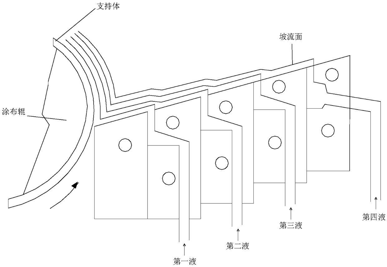
[0040] A preparation method for a composite electrolyte membrane of a solid-state battery, which is through a multi-layer slide coating process, and the PET carrier is coated with No. 1 (formation layer 1) and No. 2 slurry (formation layer 2), and No. 1 The slurry is in contact with the PET surface, and after the coating is dried and shaped, the PET carrier is peeled off. The multi-flow coating process is as follows: the organic-inorganic composite electrolyte slurry flows out from the slit of the coating die and flows down along the slope flow surface, and then forms a gap between the coating roller and the slide coating die. The liquid bridge is taken away by the running carrier to form a multi-layer coating, and after drying, the composite electrolyte membrane of the solid-state battery is obtained.

[0041] The coating speed is 1m / min, two layers are coated, the drying temperature is 70°C, the drying time is 5min, and the total thickness of the dry film is 15μm.

[0042] ...

Embodiment 2

[0044] The difference from Example 1 is:

[0045] The coating speed is 10m / min; the number of coating layers is 1; the coating thickness is 5 μm; the drying temperature is 40°C.

[0046] The organic-inorganic composite electrolyte slurry includes the following five raw materials: lithium lanthanum zirconium oxide, lithium hexafluorophosphate, polyvinylidene fluoride, polyethylene oxide, ethylene carbonate, and the mass ratio of the five raw materials is 5:1:1:1:0.1 Mix in dimethylformamide, and ball mill at 300 rpm for 1 hour to obtain organic-inorganic composite electrolyte slurry.

Embodiment 3

[0048] The difference from Example 1 is:

[0049] The coating speed is 30m / min; the number of coating layers is 10; the coating thickness is 100 μm; the drying temperature is 100°C.

[0050] The organic-inorganic composite electrolyte slurry includes the following five raw materials: lithium lanthanum zirconium oxide, lithium hexafluorophosphate, polyvinylidene fluoride, polyethylene oxide, ethylene carbonate, and the mass ratio of the five raw materials is 5:1:1:1:0.1 Mix in dimethylformamide, and ball mill at 300 rpm for 1 hour to obtain organic-inorganic composite electrolyte slurry.


PUM

PropertyMeasurementUnit
Thicknessaaaaaaaaaa
Ionic conductivityaaaaaaaaaa

Abstract

The invention discloses a preparation method for a composite electrolyte membrane of a solid-state battery. By a multi-layer slope flowing coating process, multi-layer organic-inorganic composite electrolyte paste is synchronously coated on a surface of a carrier, and the composite electrolyte membrane of the multi-layer structure solid-state battery can be prepared. The multi-current coating process comprises the following steps of preparing paste of different constituents, allowing the organic-inorganic composite electrolyte paste to downwards flow along a slope flowing current after flowingout of a gap of a coating module according to an arrangement sequence, forming a liquid bridge in a gap between a coating roller and a slope flowing coating module, taking away by the running carrier, forming one or more layers of coating, performing, and stripping the carrier, thereby obtaining the composite electrolyte membrane of the solid-state battery.

Description

technical field [0001] The invention relates to the technical field of electrolyte membranes for solid-state batteries, in particular to a method for preparing a composite electrolyte membrane for solid-state batteries. Background technique [0002] The preparation of electrolyte membrane (also known as diaphragm) is one of the core technologies of lithium-ion batteries. It plays a role in preventing positive / negative short circuit in the battery and providing ion transport channels during charging and discharging. The performance of the electrolyte membrane determines the interface structure and internal resistance of the battery, which directly affects the capacity, cycle performance, charge and discharge current density, and safety performance of the battery. A separator with excellent performance plays an important role in improving the overall performance of the battery. Compared with liquid lithium batteries, solid-state lithium batteries refer to energy storage device...

Claims


Application Information

Patent Timeline
IPC IPC(8): H01M10/056
CPCH01M10/056H01M2300/0085H01M2300/0094Y02E60/10
Inventor 林久张计娜许晓雄徐忠伟魏潇博
Owner ZHEJIANG FUNLITHIUM NEW ENERGY TECH CO LTD
Why Eureka
Try Eureka