Steel slag micro-powder selecting system utilizing waste heat flue gas of steel plant

A technology for iron and steel slag and iron and steel plants, applied in the field of iron and steel slag micropowder separation systems, can solve the problems of direct waste heat discharge, insufficient utilization, poor stability, etc., to reduce fuel costs, avoid heat loss, and fast heating. Effect

Pending Publication Date: 2018-11-23
ZHENGZHOU WOTE ELECTRONICS TECH
View PDF1 Cites 0 Cited by
  • Summary
  • Abstract
  • Description
  • Claims
  • Application Information

AI Technical Summary

Problems solved by technology

Due to the presence of free calcium oxide and magnesium oxide in the steel slag produced in steelmaking, the stability is poor, and the utilization rate is less than 20%.
In the

Method used


Image

  • Steel slag micro-powder selecting system utilizing waste heat flue gas of steel plant
  • Steel slag micro-powder selecting system utilizing waste heat flue gas of steel plant
  • Steel slag micro-powder selecting system utilizing waste heat flue gas of steel plant

Examples


Example Embodiment

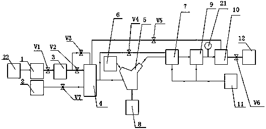
[0021] Such as figure 1 As shown, a steel slag powder separation system using waste heat flue gas from a steel plant includes a waste heat flue gas source 22 of a steel plant, a waste heat flue mechanism for gathering waste heat flue gas from multiple locations in a steel plant, and a waste heat flue gas. Pressurizing mechanism 3, coal gas source 2, supplementary combustion hot air stove 4, static powder separator 5, feeding mechanism 6, coarse material storage mechanism 8, cyclone 7, dust removal mechanism, fine material storage mechanism 11 and exhaust mechanism 12 ;

[0022] The dust removal mechanism includes a bag filter 9 and a dust removal fan 10. The gas outlet of the bag filter 9 is connected to the gas inlet of the dust removal fan 10. The bag filter 9 and the dust removal fan 10 form a two-stage dust removal mechanism to further reduce the particulate matter in the exhaust gas. , Prevent particulate matter from polluting the environment.
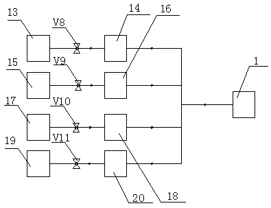
[0023] The waste heat flue gas...


PUM


Abstract

The invention discloses a steel slag micro-powder selecting system utilizing waste heat flue gas of a steel plant. The system comprises a waste heat flue gas source, a waste heat flue mechanism, a waste heat flue gas pressurizing mechanism, a gas source, an after-burning type hot air heater, a static powder selector, a feeding mechanism, a coarse material storage mechanism, a cyclone barrel, a dust removal mechanism, a fine material storage mechanism and an exhaust mechanism. The waste heat flue gas in the waste heat flue gas source sequentially enters the waste heat flue mechanism, passes thewaste heat flue pressuring mechanism and enters the after-burning type hot air heater to be heated. The waste heat flue gas enters the static powder selector from the after-burning type hot air heater, coarse materials in the static powder selector are stored in the coarse material storage mechanism, fine materials are stored in the fine material storage mechanism after being subjected to gas-material separation in the cyclone barrel, air flowing out of the cyclone barrel is filtered and exhausted through the dust removal mechanism, the air is heated into hot air in the hot air heater throughthe waste heat flue gas of waste heat of the steel plant, the waste heat flue gas of the waste heat of the steel plant is recycled, and the fuel cost in a hot air furnace is greatly reduced.

Description

[0001] The invention relates to the technical field of steel slag micropowder manufacturing, in particular to a steel slag micropowder separation system utilizing waste heat flue gas from a steel plant. Background technique [0002] At present, steel slag and slag are the metallurgical slag with the largest emissions in the iron and steel industry. According to the relevant iron-making and steel-making process, the output of steel slag is 12-15% of the crude steel output, and the slag is 25%-35% of the crude steel output. The slag produced by blast furnace smelting has great activity after water quenching. After being made into micropowder, it can be used as cement admixture and concrete admixture with a comprehensive utilization rate of more than 90%. The steel slag produced by steelmaking has poor stability due to the presence of free calcium oxide and magnesium oxide, and the utilization rate is less than 20%. At present, a promising application of steel slag is to make ste...

Claims


Application Information

Patent Timeline
IPC IPC(8): B07B9/02B07B11/06B07B11/00B01D50/00F27D17/00F24H3/00F24H9/18F24H9/00F23L7/00
CPCF23L7/00F24H3/006F24H9/0052F24H9/1881F27D17/004B07B9/02B07B11/00B07B11/06F27D2017/006B01D50/20Y02P10/25
Inventor 李勋杨勇
Owner ZHENGZHOU WOTE ELECTRONICS TECH
Why Eureka
Try Eureka