
Nuclear microporous membrane for atomizer plate and making method of nuclear microporous membrane

A technology of nuclear microporous membrane and atomized tablet, which is applied in the field of drug atomization treatment and nuclear microporous membrane ultrasonic atomized tablet, which can solve the problem of low concentration of atomized aerosol, difficulty in large-dose administration, and insufficient aerosol particle size Small and other problems, to avoid excessive temperature and improve the efficiency of use

Pending Publication Date: 2018-12-04
邻得膜科技南京有限公司
View PDF0 Cites 6 Cited by
  • Summary
  • Abstract
  • Description
  • Claims
  • Application Information

AI Technical Summary

Problems solved by technology

However, since the current microhole processing is mainly completed by laser ablation or chemical etching technology, the adjustment of the number, shape and aperture parameters of the microholes and the selection of atomizing sheet materials are greatly restricted, so that this type of atomizer exists as follows Disadvantages: 1) The concentration of atomized aerosol is low; 2) The particle size of the aerosol is not small enough, so that the volume ratio of the aerosol directly reaching the alveoli is not high; 3) The particle size distribution of the aerosol is wide, and the SR value is about 8-12
These defects cause when using this kind of nebulizer to treat pulmonary diseases, there are 1) the effective utilization rate of medicine is low; Simultaneously transported and deposited in the lungs, trachea and bronchi

Method used


Image

  • Nuclear microporous membrane for atomizer plate and making method of nuclear microporous membrane
  • Nuclear microporous membrane for atomizer plate and making method of nuclear microporous membrane
  • Nuclear microporous membrane for atomizer plate and making method of nuclear microporous membrane

Examples


Embodiment 1

[0050] 1) Kr particles with an energy of 10 MeV / u irradiate a polycarbonate film with a thickness of 10 μm to form a track density of 2×10 6 / cm 2 Submerged track membrane;

[0051] 2) Print a layer of nitrocellulose layer on one side (side A) of the latent track membrane, and the printing thickness range is 0.5 μm;

[0052] 3) Vacuum-deposit an aluminum layer with a certain thickness on the surface A of the latent track film, with a thickness ranging from 0.01 to 0.1 μm;

[0053] 4) After compounding the surface A of the creeping track film with the film with adhesive, soak in 5mol / L sodium hydroxide solution at 70°C until the aluminum layer completely disappears, take out the creeping track film, and put the composite The adhesive film is torn off and removed;

[0054] 5) Cleaning and drying, that is, the thickness is 8 μm, d=1 μm, D=3Mm, ρ=2×10 6 / cm 2 Single-cone nuclear microporous membrane;

[0055] 6) Cutting the nuclear microporous membrane of the single cone por...

Embodiment 2

[0062] 1) Kr particles with an energy of 10 MeV / u irradiate a polyester film with a thickness of 20 μm to form a track density of 2×10 5 / cm 2 Submerged track membrane;

[0063] 2) Print a layer of nitrocellulose on one side (side A) of the latent track membrane, and the printing thickness range is 1 μm;

[0064] 3) Vacuum-deposit an aluminum layer with a certain thickness on the surface A of the latent track film, with a thickness ranging from 0.01 to 0.1 μm;

[0065] 4) After compounding the surface A of the latent track film with the film with adhesive, soak it in 8mol / L potassium hydroxide + 1% potassium permanganate solution at 65°C, and observe the aluminum layer on the film When the aluminum layer disappears completely, the submerged track film is taken out, and the composite adhesive film is torn off and removed;

[0066] 5) Washing and drying, that is, the thickness is 15 μm, d=3 μm, D=10 μm, ρ=2×10 5 / cm 2 Single-cone nuclear microporous membrane;

[0067] 6) C...

Embodiment 3

[0074] 1) Kr particles with an energy of 10 MeV / u irradiate a polyimide film with a thickness of 40 μm to form a track density of 8×10 4 / cm 2 Submerged track membrane;

[0075] 2) Print a layer of nitrocellulose layer on one side (side A) of the latent track membrane, and the printing thickness range is 0.5 μm;

[0076] 3) After compounding the surface A of the latent track film with the film with adhesive, soak in 6mol / L potassium permanganate solution at 80°C for 30 minutes, take out the latent track film, and put the composite film with adhesive torn apart;

[0077] 4) Washing and drying, that is, the thickness is 32 μm, d=8 μm, D=15 μm, ρ=8×10 4 / cm 2 Single-cone nuclear microporous membrane;

[0078] 5) Cutting the prepared nuclear microporous membrane 2 into a membrane having the same diameter as the outer diameter of the annular piezoelectric ceramic;

[0079] 6) Apply a ring-shaped adhesive on the surface of the small hole of the membrane, the outer diameter of ...


PUM

PropertyMeasurementUnit
pore sizeaaaaaaaaaa
thicknessaaaaaaaaaa
thicknessaaaaaaaaaa

Abstract

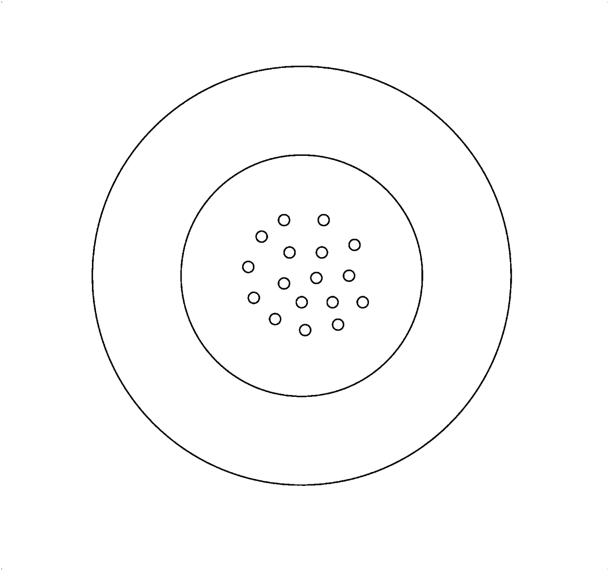
The invention provides a nuclear microporous membrane for an atomizer plate. The nuclear microporous membrane comprises a microporous area and an immobilized area, wherein the microporous area is arranged in the middle and is provided with conical micropores; and the immobilized area is arranged on the periphery of the microporous area. The nuclear microporous membrane provided by the invention has the beneficial effects that 1) particle size is controlled by pores, so that most drug particles can directly reach pulmonary alveoli, and can act on lung inflammation sites through effects of gravity deposition and dispersion deposition; 2) pore pattern of the nuclear microporous membrane can be optionally adjusted, so that a purpose of conducting passive targeted therapy can be achieved; 3) anatomizing dosage is controlled by the density of pores of the nuclear microporous membrane; therefore, drug dosage can be adjusted, and it is possible to conduct large-dose administration within a short time; 4) ultra-high frequency ultrasonic means can be avoided, so that a circumstance that partial drugs become invalid due to too high temperature of a vibrating plate can be prevented; and 5) large-dose administration can be achieved without the assistance of high-power ultrasonic wave.

Description

technical field [0001] The invention belongs to the technical field of drug atomization therapy, in particular to the technical field of nuclear microporous membrane ultrasonic atomization tablets. Background technique [0002] The purpose of drug aerosol therapy is to deliver therapeutic doses of drugs to target sites. For patients with lung lesions, compared with other administration methods, nebulized administration can achieve higher local drug concentration and reduce systemic adverse reactions. In recent years, the continuous innovation and improvement of atomization inhalation technology has improved drug output and inhalation efficiency, and increased the concentration of drugs in the lungs. [0003] Nebulization therapy mainly refers to aerosol inhalation therapy. The so-called aerosol refers to tiny solid or liquid particles suspended in the air. Therefore, atomization inhalation therapy is to disperse the drug (solution or powder) into tiny mist or particles wi...

Claims


Application Information

Patent Timeline
Patent Type & Authority Applications(China)
IPC IPC(8): A61M11/00B32B37/12B32B38/00B01D29/05
CPCA61M11/003A61M11/005B01D29/05B32B37/12B32B38/0004B05B17/0646
Inventor 何剀彦齐佳徐而翔王京史净雯
Owner 邻得膜科技南京有限公司
Learn More