Ring cavity fiber laser system

A fiber laser and ring cavity technology, applied in the field of lasers, can solve the problems of laser pulse disturbance, loss of lock of fiber lasers, etc., and achieve the effect of self-stabilization and labor cost saving.

Pending Publication Date: 2018-12-07
SHENZHEN SUPER LASER TECH
View PDF0 Cites 0 Cited by
  • Summary
  • Abstract
  • Description
  • Claims
  • Application Information

AI Technical Summary

Problems solved by technology

The polarization state of the laser pulse in the fiber is easily affected by the disturbance of the external environment.
For example, when the external temperature changes or the fiber is disturbed, the polarization state change caused by the laser pulse propagating in the fiber resonator for one cycle will also change accordingly. At this time, if the polarization controller is not adjusted accordingly, the fiber laser will lose the lock

Method used


Image

  • Ring cavity fiber laser system
  • Ring cavity fiber laser system

Examples


Embodiment Construction

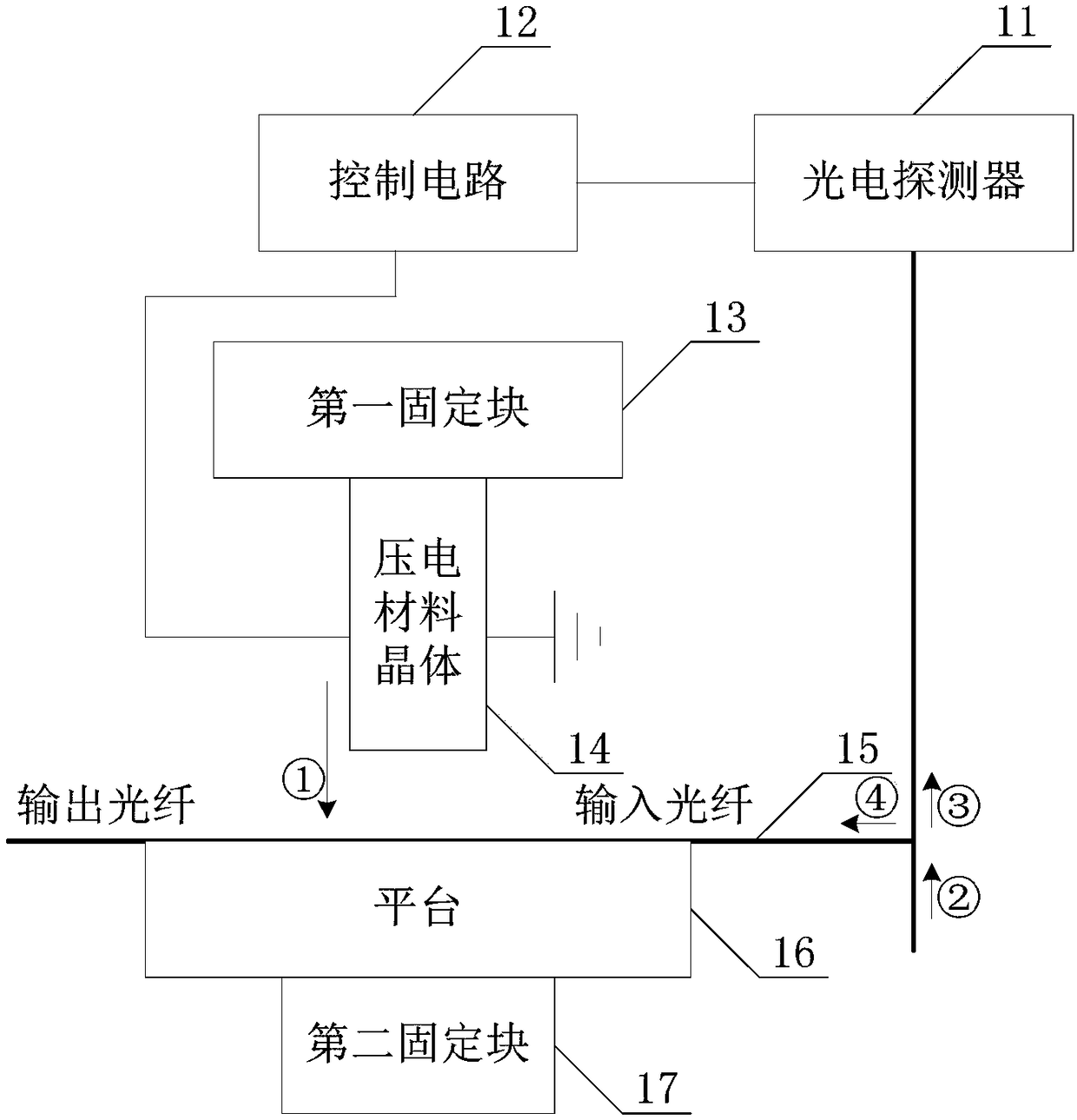
[0010] see figure 1 , figure 1 It is a structural schematic diagram of an embodiment of the optical fiber polarization control device of the present invention. Such as figure 1 As shown, the optical fiber polarization control device in the present invention is composed of two parts, namely the optical fiber polarization control device and the photodetector 11, wherein the optical fiber polarization control device includes a pressure component and a control circuit 12, and the pressure generation component includes a first fixed block 13 and piezoelectric material crystals 14 . The optical fiber 15 is arranged on the platform 16, and the platform 16 is fixed by the second fixing block 17, so that the position of the optical fiber 15 is fixed.

[0011] Wherein, the optical fiber polarization control device is coupled with the photodetector 11 . Specifically, the photodetector 11 transmits information to the control circuit 12 in a wireless / wired manner. Optionally, the phot...


PUM


Abstract

The invention discloses a ring cavity fiber laser system. The ring cavity fiber laser system includes a fiber, a laser, a fiber polarization control device, at least one coupler and an isolator, wherein a laser beam generated by the laser is input into the fiber through the coupler; the fiber polarization control device adjusts the deviation between peak intensity of the laser pulse in the fiber and an initial value within a preset range; and the fiber is connected to the isolator after passing through the fiber polarization control device, so as to enable the laser beam to be transmitted unidirectionally in the cavity. Therefore, the ring cavity fiber laser system can control the birefringence effect in the fiber in real time so as to control the polarization state of the transmitted laser in the fiber in real time.

Description

technical field [0001] The invention relates to the field of lasers, in particular to a ring cavity fiber laser system. Background technique [0002] Picosecond or femtosecond laser pulse fine processing, wafer cutting and marking, solar cell processing, curved display and other transparent materials, ophthalmic surgery, heart stent and other biomaterial processing, aerospace engine manufacturing, 3D printing and other high-end intelligent manufacturing fields have achieved more and more progress. more and more applications. [0003] Fiber mode-locked lasers are simple in structure and low in cost, and are commonly used to generate picosecond or femtosecond ultrashort laser pulses. At present, the most commonly used fiber laser mode-locking technologies mainly include nonlinear polarization rotation mode-locking and semiconductor saturable absorber mirror (SESAM)-based mode-locking technology. [0004] The nonlinear polarization rotation mode-locked fiber laser utilizes th...

Claims


Application Information

Patent Timeline
Patent Type & Authority Applications(China)
IPC IPC(8): H01S3/067H01S3/083H01S3/098
CPCH01S3/06712H01S3/083H01S3/1106
Inventor 韩侠辉
Owner SHENZHEN SUPER LASER TECH
Why Eureka
Try Eureka