Biomass carbonizing equipment and carbonizing method
A technology for biomass charcoal and chemical equipment, which is applied in chemical instruments and methods, biofuels, separation methods, etc., can solve the problems of inability to guarantee the temperature required for carbonization in a carbonization furnace, unstable product quality, and low carbonization efficiency. The effect of good quality, long production cycle and high carbonization efficiency
- Summary
- Abstract
- Description
- Claims
- Application Information
AI Technical Summary
Problems solved by technology
Method used
Image
Examples
Embodiment 1
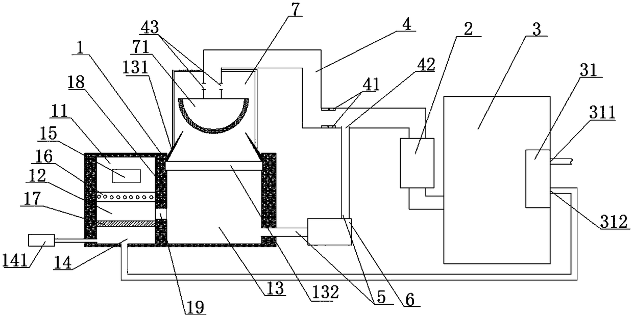
[0042] A biomass carbonization equipment, including a combustion furnace body 1, a heat pump 2, and a carbonization furnace body 3, characterized in that: the combustion furnace body 1 includes a furnace and an air inlet chamber 14 with an air inlet connected to the furnace, the The furnace is sequentially connected to the heat pump 2 and the carbonization furnace body 3 through the hot gas pipeline 4, and the hot gas pipeline 4 between the furnace and the heat pump is provided with a return port 41, and the return port 41 is sequentially connected to the return pump 6, In the furnace, the hot gas pipeline 4 on the side of the backflow port 41 near the combustion furnace body 1 is provided with a temperature detector 42, and also includes an intelligent controller. Electric connection, in this embodiment, through the control of the intelligent controller, the temperature detector 42 is used to detect the high-temperature gas generated after the fuel is burned in the furnace, an...
Embodiment 2
[0044] On the basis of Embodiment 1, the furnace is divided into a pre-combustion chamber 11, a main combustion chamber 12 and an ember chamber 13, the pre-combustion chamber 11 is provided with a fuel inlet 15, and the main combustion chamber 12 is arranged on the pre-combustion chamber. Below the combustion chamber 11, the pre-combustion chamber 11 and the main combustion chamber 12 are separated by a water-cooled fire grate 16, the ventilation chamber 14 is arranged below the main combustion chamber 12, and the main combustion chamber 12 and the ventilation chamber 14 pass through the lower fire grate 17 separated, the ember chamber 13 is arranged on one side of the main combustion chamber 12, a furnace wall 18 with a flue gas channel throat 19 is arranged between the main combustion chamber 12 and the ember chamber 13, and the hot gas pipeline 4 is connected At the high-temperature gas outlet above the ember chamber 13, the return pipe 5 is connected to the return gas inlet...
Embodiment 3
[0046] On the basis of Embodiment 1 or 2, a dust removal chamber 7 is provided above the ember chamber 13, and the exhaust end of the ember chamber 13 is provided with an exhaust passage 131 that is thin at the top and thick at the bottom. The upper end of 131 is inserted into the dust removal chamber 7, and an inverted hemispherical adsorption seat 71 is arranged in the dust removal chamber 7. The upper end surface of the hot gas pipeline 4 connected to the hemispherical adsorption seat 71 is located in the part of the hot gas pipeline in the dust removal chamber 7. 4 is provided with a hot gas outlet 43. In this embodiment, through the setting of the dust removal chamber 7, the hemispherical adsorption seat 71 is used to adsorb the micro-particle impurities in the high-temperature gas generated by combustion, and filter out the harmful substances in the high-temperature gas. , so as to avoid mixing impurities when carbonizing the biomass raw material, so that the quality of t...
PUM
 Abstract
Description
Claims
Application Information
 - R&D
- Intellectual Property
- Life Sciences
- Materials
- Tech Scout
- Unparalleled Data Quality
- Higher Quality Content
- 60% Fewer Hallucinations
Browse by: Latest US Patents, China's latest patents, Technical Efficacy Thesaurus, Application Domain, Technology Topic, Popular Technical Reports.
© 2025 PatSnap. All rights reserved.Legal|Privacy policy|Modern Slavery Act Transparency Statement|Sitemap|About US| Contact US: help@patsnap.com

