Fuel cell-based distributed energy system using liquefied natural gas as feedstock

A liquefied natural gas and distributed energy technology, applied in fuel cells, fuel cell additives, circuits, etc., can solve problems such as energy waste and cold pollution, achieve high controllability and flexibility, low pollution, and full utilization Effect

Pending Publication Date: 2018-12-21
CHINA UNIV OF PETROLEUM (BEIJING)
View PDF0 Cites 10 Cited by
  • Summary
  • Abstract
  • Description
  • Claims
  • Application Information

AI Technical Summary

Problems solved by technology

Most of the LNG satellite stations built in China directly gasify LNG, and a large amount of cold energy generated is taken aw

Method used


Image

  • Fuel cell-based distributed energy system using liquefied natural gas as feedstock
  • Fuel cell-based distributed energy system using liquefied natural gas as feedstock
  • Fuel cell-based distributed energy system using liquefied natural gas as feedstock

Examples


Example Embodiment

[0070] Example one

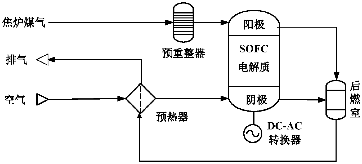
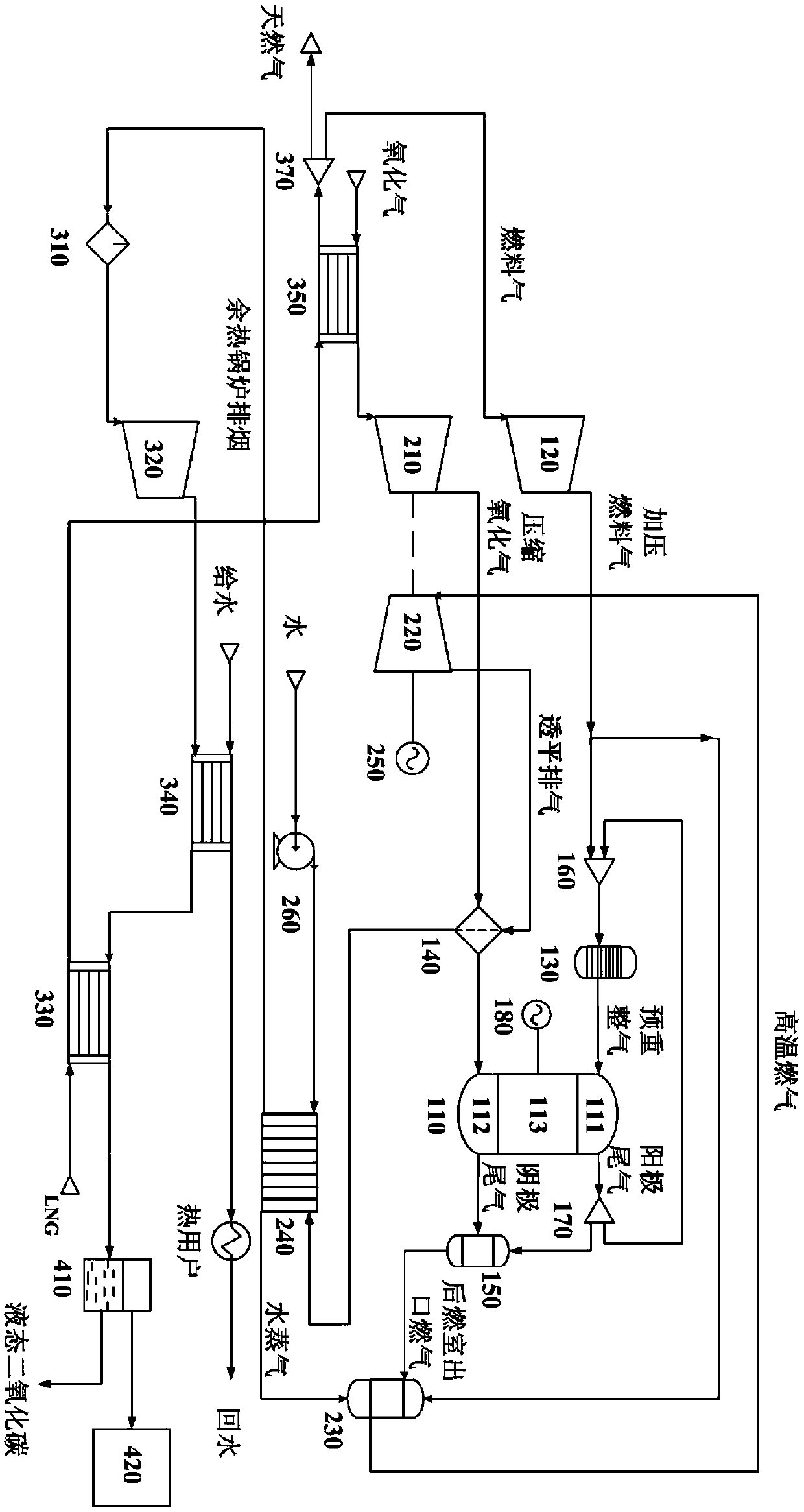
[0071] image 3 It is a schematic structural diagram of a fuel cell-based distributed energy system using liquefied natural gas as a raw material provided by an embodiment of the present invention. Such as image 3 As shown, this embodiment provides a fuel cell-based distributed energy system using liquefied natural gas as a raw material, including a solid oxide fuel cell subsystem, a steam injection gas turbine subsystem, and a liquefied natural gas refrigeration subsystem:

[0072] The solid oxide fuel cell subsystem includes a solid oxide fuel cell stack (not shown), a fuel compressor 120, a pre-reformer 130, a preheater 140, and an afterburner 150. The solid oxide fuel cell stack includes multiple A solid oxide fuel cell 110. The solid oxide fuel cell 110 has a cathode inlet and an anode inlet for oxidizing gas and fuel gas respectively, and a cathode outlet and an anode outlet for discharging cathode tail gas and anode tail gas respectively;

[0073] The ...

Example Embodiment

[0114] Example two

[0115] The distributed energy system in the first embodiment is used for energy utilization. The main simulation conditions of the distributed energy system under specific working conditions are shown in Table 1, and the corresponding energy balance table is shown in Table 2; The balance sheet is shown in Table 3.

[0116] Table 1 Energy system simulation conditions

[0117]

[0118] Table 2 System Energy Balance Sheet

[0119]

[0120]

[0121] Table 3 System Balance sheet

[0122]

[0123]

[0124] The calculation results in the above table show that under the design conditions, the total electrical efficiency, total thermal efficiency and total thermal efficiency of the distributed energy system The efficiencies are 57.08%, 72.77%, and 61.9%, and liquid CO with a temperature of -69°C and a pressure of 0.3MPa is recovered. 2 The mass flow rate is 12.46kmol / h.

[0125] It can be seen that the SOFC-STIG new distributed energy system using LNG as fuel proposed by t...


PUM


Abstract

The invention provides a distributed energy system based on fuel cell using liquefied natural gas as raw material, which comprises a solid oxide fuel cell subsystem, a steam injection gas turbine subsystem and a liquefied natural gas refrigeration subsystem. An outlet of the fuel compressor is communicated with an inlet of the preformer and an inlet of the combustion chamber respectively; An outlet of the aftercombustion chamber is communicated with an inlet of the combustion chamber; An outlet of the combustion chamber communicates with an inlet of the gas turbine; The heat medium inlet of the waste heat boiler is communicated with the outlet of the gas turbine through the preheater, the heat medium outlet is communicated with the inlet of the first heat release passage of the first condenser, and the cold medium outlet is communicated with the inlet of the combustion chamber. An inlet of the first endothermic passage of the first condenser is in communication with the LNG satellite station, and an outlet of the first endothermic passage is in communication with an inlet of the fuel compressor. The distributed energy system provided by the invention not only optimizes the energy structure but also saves energy and environmental protection, and has important guiding significance for the rational utilization of the energy of the LNG satellite station in China.

Description

technical field [0001] The invention relates to a fuel cell-based distributed energy system using liquefied natural gas as a raw material, in particular to a solid oxide fuel cell-steam injection gas turbine-liquefied natural gas refrigeration distributed energy system using liquefied natural gas as a raw material. Background technique [0002] The main component of liquefied natural gas (LNG) is methane, which has the characteristics of large calorific value and high performance, and is a clean and efficient energy source. According to the current LNG use plan, by 2020, China's LNG demand will reach 46 million tons, and 25 million tons of LNG will need to be imported by then. In recent years, with the increase of LNG imports, many LNG satellite stations have been established in China's inland areas in order to improve the capacity of LNG reception, storage, gasification and transportation. [0003] When the liquefied natural gas is vaporized, a large amount of cold energy ...

Claims


Application Information

Patent Timeline
IPC IPC(8): H01M8/04089H01M8/0612H01M8/0662H01M8/1231F02C6/00
CPCH01M8/04201H01M8/0618H01M8/0662H01M8/1231F02C6/00H01M2008/1293Y02E60/50
Inventor 赵洪滨杨晓宇侯秦龙
Owner CHINA UNIV OF PETROLEUM (BEIJING)
Why Eureka
Try Eureka