Method and device for measuring axial clearance of rear spectrophotometric pupil laser differential confocal lens group

A technology of differential confocal and axial gap, which is applied in the direction of measuring devices, optical devices, instruments, etc., can solve the problem of unsatisfactory high-precision testing of the axial gap of the lens group, and achieve the effect of improving the precision of the fixed focus

Active Publication Date: 2019-01-11
BEIJING INSTITUTE OF TECHNOLOGYGY
View PDF8 Cites 7 Cited by
  • Summary
  • Abstract
  • Description
  • Claims
  • Application Information

AI Technical Summary

Problems solved by technology

[0013] The purpose of the present invention is to solve the unsatisfactory problem of unsatisfactory high-precision testing of the axial gap of the mirror group, and propose a post-divided-pupil laser differential detection system that collects the measuring beam through the rear pupil and uses the sub-pupil differential confocal detection system Method and device for measuring axial gap of confocal lens group

Method used


Image

  • Method and device for measuring axial clearance of rear spectrophotometric pupil laser differential confocal lens group
  • Method and device for measuring axial clearance of rear spectrophotometric pupil laser differential confocal lens group
  • Method and device for measuring axial clearance of rear spectrophotometric pupil laser differential confocal lens group

Examples


Embodiment 1

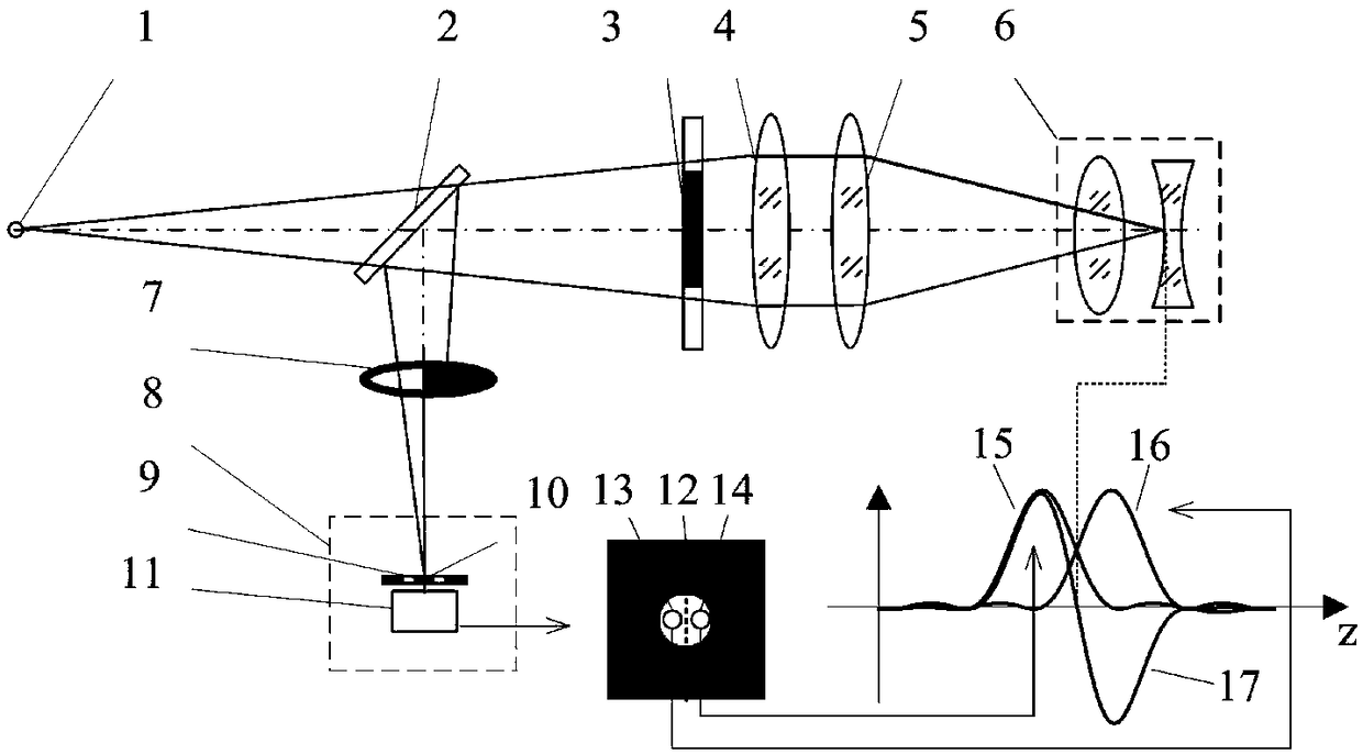
[0049] Such as Figure 4 As shown, the axial gap measurement device of the rear split pupil laser differential confocal lens group includes a laser 22, an optical fiber 23 and a point light source 1, which are sequentially placed in the beam splitter 2 and collimator lens 3 in the direction of the light emitted by the point light source 1 And converging lens 4, also comprises the D-shaped rear pupil 7 that is placed in the reflection direction of beam splitter 2 and the split pupil differential confocal detection system 8 that is made of microscope objective lens 20 and CCD21; Main control computer 24 and motor drive The system 25 is connected so that it drives the linear guide rail 26 to drive the measured lens group 6 to scan along the optical axis.

[0050] When the device is used to measure the axial gap of the lens group, the split-pupil differential confocal measurement system 8 in the system is used to position the vertices of each surface of the measured lens group 6 w...

Embodiment 2

[0062]Such as Figure 5 As shown, the axial gap measurement device of the rear split-pupil laser differential confocal lens group, the measurement steps are:

[0063] (1) Start the measurement software in the main control computer 24, turn on the laser 22, and the light emitted by the laser 22 is transmitted through the optical fiber 23 to form the point light source 1. The light emitted by the point light source 1 forms a measuring beam after passing through the beam splitter 2, the collimating lens 4 and the converging lens 5;

[0064] (2) Input the parameters of the measured lens group 6 in the measurement software, and the curvature radius from left to right is: r 1 =195.426mm, r 2 =-140.270mm, r 3 =-140.258mm, r 4 =400.906mm, the refractive index from left to right is: n 0 = 1, n 1 = 1.5143, n 2 = 1, n 3 = 1.668615;

[0065] (3) The measured lens group 6 is fixed on the five-dimensional adjustment frame 27, the measuring beam is irradiated on the measured lens gr...


PUM


Abstract

The invention relates to a method and device for measuring the axial clearance of a rear spectrophotometric pupil laser differential confocal lens group, and belongs to the technical field of opticalprecision measurement. According to the method in the invention, half measurement beams are kept out by utilization of a rear pupil; measurement beams are detected by utilization of a spectrophotometric pupil laser differential confocal detection system; various surface positions of the measured lens group are respectively fixed by utilization of the absolute zero point of a differential confocalresponse curve; and each axial clearance in the lens group is calculated through tracing and a compensation model thereof. According to the method and the device in the invention, a rear spectrophotometric pupil laser differential confocal technology is used for high-precision detection of the axial clearance of the lens group for the first time; differential confocal focus-fixing can be realizedonly by one detector; a laser differential confocal technology and a ray tracing technology are organically fused; influence among various focused surface parameters is eliminated; furthermore, the data near the absolute zero point is linearly fitted, so that quick trigger focusing is realized; the problem that the focus-fixing precision is decreased possibly due to replacement of the measured lens is avoided; and the measurement speed and precision and the anti-scattering capability are greatly improved.

Description

technical field [0001] The invention relates to a method and a device for measuring the axial gap of a post-divided pupil laser differential confocal lens group, which can be used for non-contact high-precision measurement of the axial gap in the lens group, and belongs to the technical field of optical precision measurement. Background technique [0002] In the field of optics, the measurement of the axial gap in the lens group is of great significance. During the assembly process of high-performance optical systems such as lithography objective lenses and aerospace cameras, it is necessary to precisely adjust the lens axial gap, radial offset and optical axis deflection angle according to the curvature radius and refractive index of the lens in the lens. Taking the objective lens of lithography machine as an example, the axial gap deviation of each single lens will cause spherical aberration, astigmatism, coma, distortion and other aberrations of the lithography objective ...

Claims


Application Information

Patent Timeline
Patent Type & Authority Applications(China)
IPC IPC(8): G01B11/14
CPCG01B11/14
Inventor 赵维谦杨帅王允卜乙禄
Owner BEIJING INSTITUTE OF TECHNOLOGYGY
Why Eureka
Try Eureka