Sludge treatment system

A technology of sludge treatment and treatment method, which is applied in the fields of sludge treatment, water/sludge/sewage treatment, dehydration/drying/concentrated sludge treatment, etc. The problems of difficult dehydration of the filter press and high personnel management costs have achieved the effect of convenient general layout layout, reduced scale, and low personnel management costs.

Inactive Publication Date: 2019-01-15
宝武水务科技有限公司
View PDF5 Cites 4 Cited by
  • Summary
  • Abstract
  • Description
  • Claims
  • Application Information

AI Technical Summary

Problems solved by technology

[0005] The above-mentioned sludge treatment method has complicated system flow, many facilities, many equipments, a large area, and needs to add a large amount of chemical agents. The operation is difficult and the cost of personnel management is also high.
Hot rolling or continuous casting sludge often contains oil. It is difficult to dehydrate the plate and frame filter press, and the filter cloth is easy to be fouled. Therefore, a large amount of lime needs to be added, resulting in a substantial increase in the amount of dry sludge. Can only run intermittently
The use of belt filter press also requires a large amount of lime, and the dehydration rate is low and the amount of mud cake is large
In addition, in the past, many iron and steel enterprises did not have sludge treatment
With the increasing requirements for product upgrading and environmental protection, iron and steel enterprises have begun to build a large number of sludge treatment systems. However, in the past, the layout of water treatment made it difficult to build large-scale sludge treatment systems nearby.

Method used


Image

  • Sludge treatment system
  • Sludge treatment system
  • Sludge treatment system

Examples


Embodiment Construction

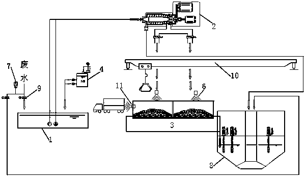
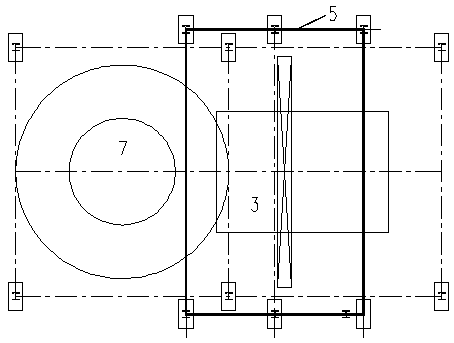
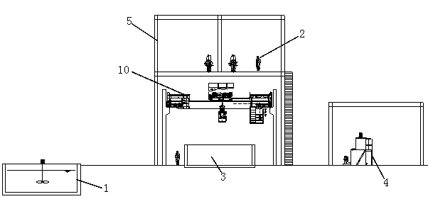
[0034] The following will combine figure 1 , figure 2 and image 3 The sludge treatment system and method provided by the present invention are described in detail, which is an available embodiment of the present invention, and it can be considered that those skilled in the art can modify and polish it within the scope of not changing the spirit and content of the present invention .

[0035] like figure 1 Shown: a sludge treatment system, which includes a regulating tank 1, a centrifugal dehydrator 2, a sludge tank 3, a station frame 5 and a dosing device 4, and the station frame is combined with a swirling well or an iron pit It is set up as two floors from top to bottom, the swirl well or iron sheet pit and the sludge tank are adjacently arranged and located on the bottom layer of the station building frame, and the centrifugal dehydrator is located on the second floor of the station building and above the sludge tank; The regulating tank, the centrifugal dehydrator, a...


PUM


Abstract

The invention relates to a sludge treatment system. The sludge treatment system comprises an adjusting tank, a centrifugal dehydrator, a sludge groove, a flocculant feeding device and the like. The sludge treatment system has the advantages that the adjusting tank is used for selecting and collecting high-concentration hot-rolling or continuous-casting turbid circulating wastewater, so that the efficiency of the sludge treatment system is improved, and the sludge treatment scale is reduced; the centrifugal dehydrator is small in size, high in pre-dehydration efficiency and low in equipment operation requirement; the sludge groove is used as a turbid circulating water treatment slag pit and is also used as a sludge dehydration facility for collecting oxidized steel and hot-rolling or continuous-casting sludge; the flocculant feeding device only needs to feed a flocculant into the adjusting tank; the sludge treatment system is simple in process, less facilities and less equipment are needed, continuous operation is realized, and the investment cost is low; a large amount of chemical agents do not need to be added in sludge treatment, lime does not need to be added, the amount of generated dry sludge is small, the operation is convenient, and the personnel management cost is low; and the system adopts the three-dimensional arrangement, the occupied area of a water station is optimized to the maximum degree, the general layout is very convenient, every single space can be made use of, and the sludge treatment system is suitable for a new project and is also suitable for technical innovation.

Description

technical field [0001] The invention relates to the field of hot rolling or continuous casting equipment for metal casting, in particular to a sludge treatment system. Background technique [0002] Hot rolling turbid ring water in iron and steel enterprises is mainly produced in the process of various roll cooling, conveying roller table cooling, high-pressure descaling (washing scale and slag), and continuous casting turbid ring water is mainly produced in secondary spray cooling and equipment Water for direct cooling, flame cutting machine and billet slag granulation, rapid water cooling device and flame cleaning machine, etc. During the generation of turbid ring water, not only the water temperature will rise, but the water quality will also be polluted. The main pollutants in the turbid ring water are suspended iron oxide scale solid phase particles and various oil stains. [0003] At present, the commonly used water treatment processes for hot rolling or continuous cas...

Claims


Application Information

Patent Timeline
Patent Type & Authority Applications(China)
IPC IPC(8): C02F11/00C02F11/143C02F11/127C02F103/16
CPCC02F11/00C02F11/12C02F11/127C02F11/14C02F2103/16
Inventor 金亚飚陈琦田麟刘松邱玲峰
Owner 宝武水务科技有限公司
Why Eureka
Try Eureka