Eureka AIR delivers breakthrough ideas for toughest innovation challenges, trusted by R&D personnel around the world.

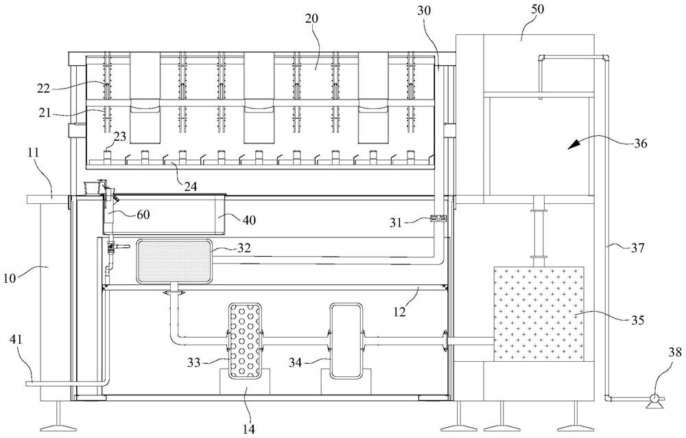
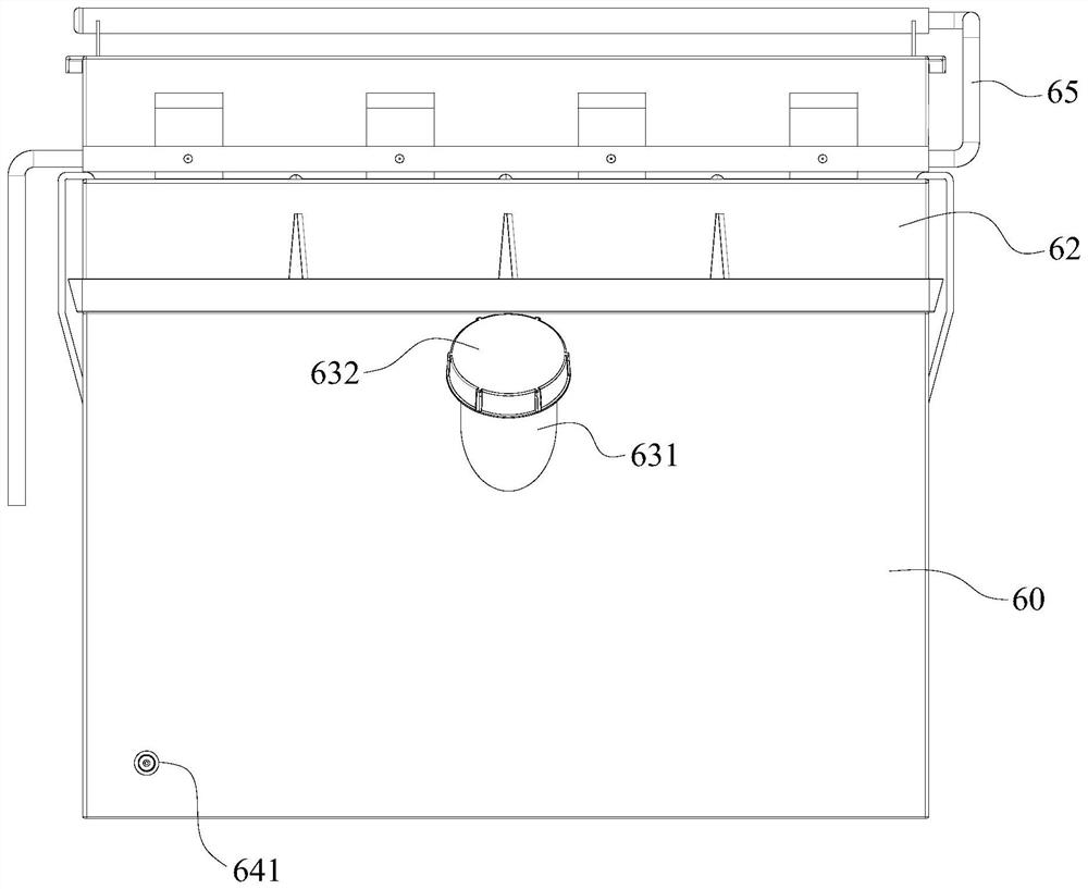
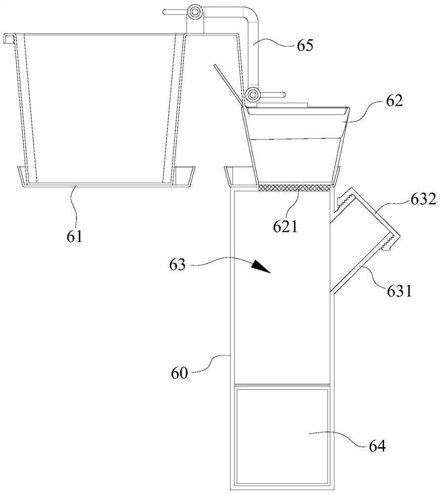
A corrosion test device for low-magnification inspection of dendrite corrosion

A technology of low-magnification inspection and corrosion test, which is applied in the field of chemical analysis and detection, can solve the problems of complex processing steps, achieve the effect of convenient waste acid treatment and avoid damage

Active Publication Date: 2021-09-07
SHENYANG QIGUANG TECH CO LTD
View PDF8 Cites 0 Cited by
  • Summary
  • Abstract
  • Description
  • Claims
  • Application Information

AI Technical Summary

Problems solved by technology

[0004] Traditional dendritic corrosion low-magnification test corrosive agents cannot meet the current defect detection of high value-added ferrous metals, such as nuclear power steel, aircraft carrier plate steel, special high-temperature alloy steel, etc., and with the improvement of smelting process With continuous improvement, the defects of the product itself are decreasing day by day. Only through the construction and improvement of the solidification structure can the designed varieties achieve the proper performance, which cannot be achieved by traditional low-magnification inspections.
Moreover, most of the corrosive agents used in the existing dendrite corrosion low-magnification inspection methods contain strong acids, and the spent acid needs to be neutralized after the experiment is completed. The general neutralization treatment is neutralized by adding alkali, but this reaction requires The lye is configured and the pH needs to be tested. The processing steps are relatively complicated. Once the lye is excessive, it needs to be adjusted again, so the processing method needs to be improved.

Method used


Image

  • A corrosion test device for low-magnification inspection of dendrite corrosion
  • A corrosion test device for low-magnification inspection of dendrite corrosion
  • A corrosion test device for low-magnification inspection of dendrite corrosion

Examples


Embodiment Construction

[0022] Embodiments of the present invention provides a first etchant for etching dendrite low magnification inspection of the components etchant comprising successively, in mass percent: copper chloride (CuCl 2 ) From 0.01% to 1.0%, copper nitrate (Cu (NO 3 ) 2 ) From 0.01% to 1.5%, magnesium chloride (MgCl 2 ) From 0.01% to 1.5%, iron chloride (FeCl 3 ) From 0.01% to 3.0%, ferrous chloride (FeCl 2 ) From 0.01% to 2.0%, 1.0% to 4.0% hydrochloric acid, 40% to 50% ethanol, the balance being water. Wherein the mass concentration of hydrochloric acid: 29% to 34%.

[0023] Etchant and content of each component is preferably as follows: copper 0.1% to 0.8% chloride, copper nitrate, 0.1% to 0.8%, 0.1% to 0.8% magnesium chloride, ferric chloride, 0.1% to 2.0%, 0.1% ferrous chloride to 1.5%, from 2.0% to 3.0% HCl, 42% ethanol to 48% and the balance is water.

[0024] The components in the etchant in mass percent is more preferably: copper chloride 0.15% to 0.6%, of copper nitrate, 0.15% to...


PUM

PropertyMeasurementUnit
roughnessaaaaaaaaaa

Abstract

The invention relates to an etchant for low-magnification inspection of dendrite corrosion, which belongs to the technical field of chemical analysis and detection. The components in the etchant include: 0.01% to 1.0% of copper chloride and 0.01% to 1.5% of copper nitrate in sequence according to mass percentage , 0.01% to 1.5% of magnesium chloride, 0.01% to 3.0% of ferric chloride, 0.01% to 2.0% of ferrous chloride, 1.0% to 4.0% of hydrochloric acid, 40% to 50% of absolute ethanol, and the balance is water. The above technical solution improves the detection range of ferrous metal species by optimizing the selection of the components of the corrosive agent. The present invention also relates to a waste liquid treatment system for the corrosive agent. Aiming at the problem that the hydrochloric acid contained in the corrosive agent has a high concentration and escapes into the air during the corrosion process, a fume hood is designed as a set, and it is suitable for the corrosion process. The hydrochloric acid in the air is extracted to avoid damage to the operator's respiratory tract; at the same time, the waste acid generated during the corrosion process is collected centrally through the integrated treatment box to facilitate waste acid treatment.

Description

Technical field [0001] The present invention relates to a corrosion test apparatus for testing low-power dendrite corrosion, which belongs to the field of chemical analysis of detection. Background technique [0002] Dendrite times lower corrosion test method with the development of continuous casting technology and improving the low slab-fold test. Compared with the conventional sulfur printing times and other low thermal etching test, it can not only accurately show the internal defects in the slab, but also clearly show the solidification structure of the slab. This is a further analysis of relevant information between the slab solidification defects and organizations to explore ways to improve the quality of the slab and measures to create favorable conditions. [0003] Dendrite Corrosion testing method macroscopic sample testing side etching is electrochemical processes, chemical etching to rely display unevenness of the sample surface. In the electrolyte solution, the metal...

Claims


Application Information

Patent Timeline
Patent Type & Authority Patents(China)
IPC IPC(8): G01N1/32C23F1/08C23F1/28
CPCC23F1/08C23F1/28G01N1/32
Inventor 杨撷光许庆太
Owner SHENYANG QIGUANG TECH CO LTD
Why Eureka
Eureka Blog
Learn More