
Semiconductor device structure and fabrication method thereof

A device structure and semiconductor technology, applied in the direction of semiconductor devices, semiconductor/solid-state device manufacturing, electric solid-state devices, etc., can solve the problems that affect the batch production of semiconductor devices, channel length reduction, high manufacturing cost, etc., to reduce short channel effect, reducing the voltage required for turn-off, and increasing the migration effect

Active Publication Date: 2020-12-08
SIEN QINGDAO INTEGRATED CIRCUITS CO LTD
View PDF4 Cites 0 Cited by
  • Summary
  • Abstract
  • Description
  • Claims
  • Application Information

AI Technical Summary

Problems solved by technology

However, when the channel length of the device enters the deep nanometer scale, the doping concentration of the source-drain abrupt PN junction of the traditional inversion channel device needs to change several orders of magnitude within a few nanometers. The realization of such a large concentration gradient is very important for doping technology. The design will bring great difficulties, and the manufacturing cost of these complex processes is very high, which affects the mass production of semiconductor devices
In addition, the limit size of the space charge region of the mutant PN junction is on the order of nanometers, so the existence of the mutant PN junction physically limits the further reduction of the channel length

Method used


Image

  • Semiconductor device structure and fabrication method thereof
  • Semiconductor device structure and fabrication method thereof
  • Semiconductor device structure and fabrication method thereof

Examples


Embodiment Construction

[0062] Embodiments of the present invention are described below through specific examples, and those skilled in the art can easily understand other advantages and effects of the present invention from the content disclosed in this specification. The present invention can also be implemented or applied through other different specific implementation modes, and various modifications or changes can be made to the details in this specification based on different viewpoints and applications without departing from the spirit of the present invention.

[0063] see Figure 2 to Figure 13 . It should be noted that the diagrams provided in this embodiment are only schematically illustrating the basic idea of ​​the present invention, so that only the components related to the present invention are shown in the diagrams rather than the number, shape and Dimensional drawing, the type, quantity and proportion of each component can be changed arbitrarily during actual implementation, and th...


PUM

PropertyMeasurementUnit
thicknessaaaaaaaaaa
thicknessaaaaaaaaaa

Abstract

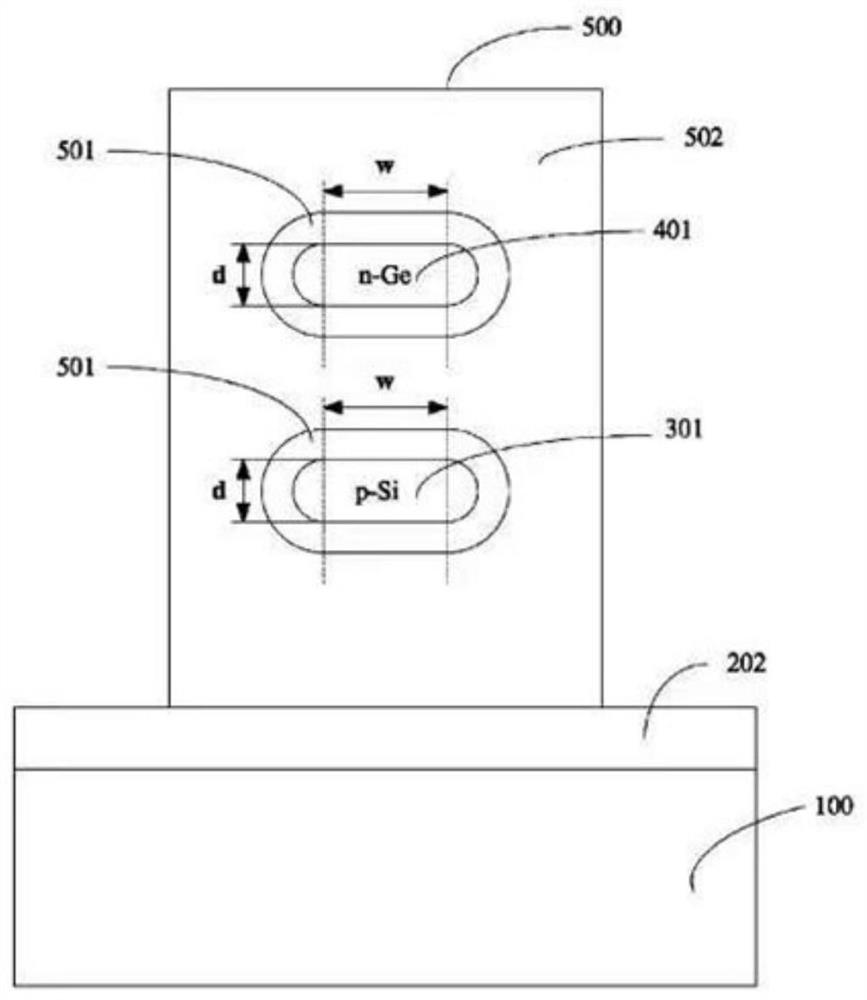
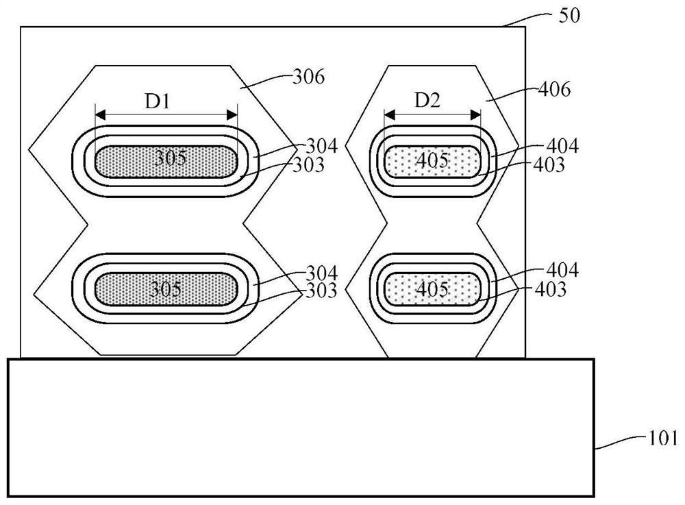
The invention provides a semiconductor device structure and a manufacturing method thereof. The structure includes: a substrate; a P-type semiconductor channel and an N-type semiconductor channel suspended on the substrate; a gate dielectric layer surrounding the P-type semiconductor channel and the N-type semiconductor channel. Semiconductor channel; gate electrode layer, surrounding the gate dielectric layer; P-type source region and P-type drain region, connected to both ends of the P-type semiconductor channel; N-type source region and N-type drain region, connected to the N-type semiconductor channel The two ends of the channel; wherein, the P-type ion doping concentration of the P-type semiconductor channel gradually decreases from the surface of the P-type semiconductor channel to the center, and the N-type ion doping concentration of the N-type semiconductor channel decreases from the N-type semiconductor channel. The surface of the channel gradually decreases toward the center, and the cross-sectional width of the P-type semiconductor channel is greater than that of the N-type semiconductor channel. The invention can realize multi-layer stacking of devices in a unit area, effectively shorten channel length, reduce short channel effect, and improve the load capacity of the device and the control ability of the gate to the channel.

Description

technical field [0001] The invention belongs to the design and manufacture of integrated circuits, in particular to a three-dimensional stacked junctionless gradient doped channel semiconductor device structure and a manufacturing method thereof. Background technique [0002] With the continuous development of semiconductor technology, the size of semiconductor devices is continuously reduced, the performance of driving current is continuously improved, and the power consumption is continuously reduced. production cost. [0003] Fin Field-Effect Transistor (FinFET) is a new complementary metal oxide semiconductor transistor. The shape of FinFET is similar to that of a fish fin. This design can improve circuit control and reduce leakage current, shortening the gate length of transistors. [0004] FinFET is an innovative design derived from the traditional standard transistor—Field-Effect Transistor (FET). In the traditional transistor structure, the gate can only control t...

Claims


Application Information

Patent Timeline
Patent Type & Authority Patents(China)
IPC IPC(8): H01L27/092H01L29/10H01L29/16H01L29/423H01L29/78H01L21/8238
CPCH01L21/823807H01L21/823821H01L21/823828H01L27/0922H01L27/0924H01L29/1033H01L29/1608H01L29/42356H01L29/785B82Y10/00H01L27/092H01L29/0673H01L29/105H01L29/16H01L29/167H01L29/42392H01L29/66439H01L29/775H01L29/78696H01L21/823814H01L21/845H01L27/1211
Inventor 肖德元张汝京
Owner SIEN QINGDAO INTEGRATED CIRCUITS CO LTD
Learn More