
Multi-element resonant converter

A resonant converter, multi-component technology, applied in electrical components, instruments, DC power input conversion to DC power output and other directions, can solve the problems of increased loss, complex control method, slow gain reduction, etc., to achieve low voltage stress, conversion The effect of high efficiency and wide gain range

Inactive Publication Date: 2019-02-19
YANSHAN UNIV
View PDF4 Cites 2 Cited by
  • Summary
  • Abstract
  • Description
  • Claims
  • Application Information

AI Technical Summary

Problems solved by technology

When the switching frequency is lower than the resonant frequency point, the gain of the converter responds quickly to changes in frequency, but when it is higher than the resonant frequency point, as the frequency increases, the gain decreases slowly. When the adjusted frequency is too high, the loss will increase. , which is not conducive to high-efficiency operation, indicating that it is difficult for LLC resonant converters to balance between wide gain and high efficiency
Therefore, a hybrid control strategy for LLC converters is proposed in the prior art, using phase-shift control for points above the resonance frequency and frequency conversion control for points below the resonance frequency to achieve a wider voltage gain, but the control method is more complicated and switching is troublesome
In order to overcome the shortcomings of LLC converters that it is difficult to balance wide gain and high efficiency, it is urgent to explore a new multi-element resonant converter topology

Method used


Image

  • Multi-element resonant converter
  • Multi-element resonant converter
  • Multi-element resonant converter

Examples


Embodiment 1

[0034] Embodiment 1 of the present invention will be described in detail below in conjunction with the accompanying drawings.

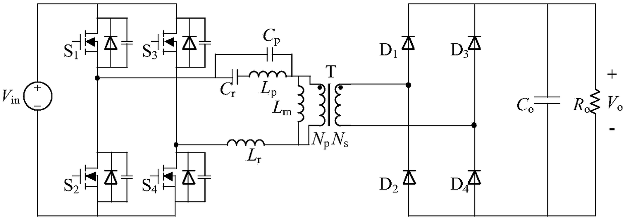
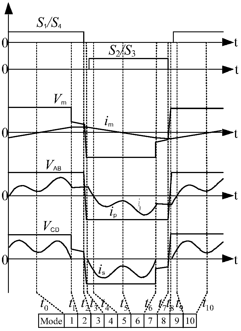
[0035] attached figure 2 It is the schematic circuit diagram of the embodiment 1 of the multi-element resonant converter of the present invention. As shown in the figure, the multi-element resonant converter includes a DC bus input circuit, a square wave generator, a resonant circuit, a transformer, a rectifying and filtering circuit, and a load, wherein The output end of the DC bus input circuit is connected to the input end of the square wave generator, the output end of the square wave generator is connected to the input end of the resonant circuit, and the resonant circuit generates a saddle wave resonant signal , the output end of the resonant circuit is connected to the primary side of the transformer, the secondary side of the transformer is connected to the input end of the rectification filter circuit, and the output end of the rectification...


PUM


Abstract

The invention discloses a multi-element resonant converter. The multi-element resonant converter comprises a direct current bus input circuit, a square wave generator, a resonance circuit, a transformer, a rectifying and filtering circuit, and a load. The output end of the direct current bus input circuit is connected with the input end of the square wave generator. The output end of the square wave generator is connected with the input end of the resonance circuit. The resonance circuit generates a resonance signal of a saddle-shaped wave, and the output end is connected with an original edgeof the transformer. An auxiliary edge of the transformer is connected with the input end of the rectifying and filtering circuit. The output end of the rectifying and filtering circuit is connected with the load. A switching tube of the multi-element resonant converter is capable of realizing zero-voltage switching-on within a whole working range and in a load condition, a grain range is wide, and a fundamental wave and a third-harmonic wave can be simultaneously used for transmitting energy.

Description

technical field [0001] The invention relates to the technical field of power electronic converters, in particular to a multi-element resonant converter. Background technique [0002] With the development of power electronics technology, wide-gain DC converters have very important applications in portable devices, electric vehicle on-board chargers, energy storage systems, communication power supplies and other fields. [0003] The LLC resonant converter has natural soft switching characteristics. The primary side switch can realize zero-voltage turn-on, and the secondary side diode can realize zero-current turn-off when it is lower than the resonance frequency. The realization of soft switching can improve the efficiency of the switch tube while ensuring the efficiency. The operating frequency; in addition, the leakage inductance of the transformer can be partially or completely used as a resonant inductor, which is convenient for magnetic integration and further improves th...

Claims


Application Information

Patent Timeline
Patent Type & Authority Applications(China)
IPC IPC(8): H02M3/335H02M1/32
CPCH02M1/32H02M3/33523H02M3/33569H02M1/0058Y02B70/10
Inventor 赵清林刘威李昆仑王德玉杨秋霞
Owner YANSHAN UNIV
Learn More