Laser cutting method and device for light filter

A laser cutting and optical filter technology, which is applied in laser welding equipment, metal processing equipment, welding equipment, etc., can solve the problems of poor cutting quality and achieve good straightness

Active Publication Date: 2019-04-16
深圳市大族半导体装备科技有限公司
View PDF7 Cites 4 Cited by
  • Summary
  • Abstract
  • Description
  • Claims
  • Application Information

AI Technical Summary

Problems solved by technology

[0007] In view of the above-mentioned deficiencies in the prior art, the object of the present invention is to provide a laser cutting method and device for optical filters, thereby overcoming the problem of poor cutting quality of existing optical filter cutting methods

Method used


Image

  • Laser cutting method and device for light filter
  • Laser cutting method and device for light filter
  • Laser cutting method and device for light filter

Examples


Embodiment Construction

[0036] The present invention provides a laser cutting method and device for an optical filter. In order to make the purpose, technical solution and effect of the present invention clearer and clearer, the present invention will be further described in detail below with reference to the accompanying drawings and examples. It should be understood that the specific embodiments described here are only used to explain the present invention, not to limit the present invention.

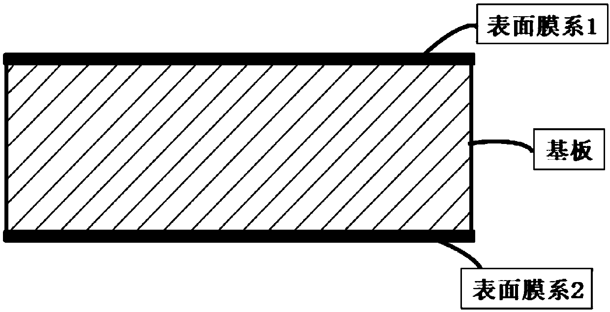
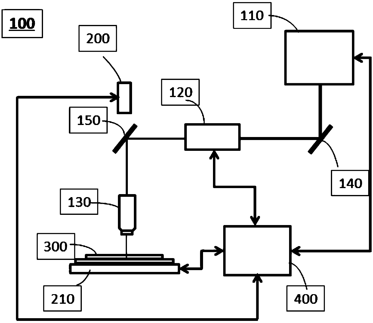
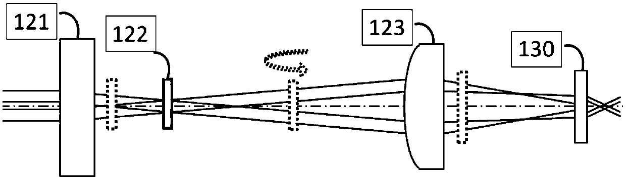
[0037] see figure 2 As shown, a laser cutting device 100 for an optical filter provided by an embodiment of the present invention includes: an ultrafast laser 110, a beam shaping module 120, a focusing objective lens 130, a visual inspection device 200, and a moving platform 210; , the visual inspection device 200 is positioned at the top of the focusing objective lens 130, and the moving platform 210 is positioned at the bottom of the focusing objective lens 130 for carrying the optical filter 300, and the...


PUM


Abstract

The invention discloses a laser cutting method and device for a light filter. The laser cutting device comprises an ultrafast laser device, a light beam shaping module, a focusing objective lens, a visual detection device and a moving platform, wherein the visual detection device is located at the upper portion of the focusing objective lens, the moving platform is located at the lower portion ofthe focusing objective lens to be used for bearing the light filter, the focusing objective lens is an imaging objective lens of the visual detection device, the ultrafast laser device emits an ultrashort pulse laser beam into the light beam shaping module, the ultrashort pulse laser beam is shaped into a linear non-diffracting light beam of evenly-distributed energy to be emitted into the focusing objective lens, and the linear non-diffracting light beam is focused by the focusing objective lens to form a high-energy-density non-diffracting light beam for cutting the light filter. According to all elements cut and obtained by the laser cutting method and device, the sections and the upper and lower surfaces are all formed regularly, the straightness is good, surface film layers have no obvious damage, and the thickness and position of modified layers formed in the cutting process can be selected according to the thickness of a base plate or the actual requirements to meet the machining requirements for different specifications.

Description

technical field [0001] The invention relates to the technical field of laser processing, in particular to a laser cutting method and device for an optical filter. Background technique [0002] As an optical element that can pass or cut off specific wavelengths, the optical filter is a key functional component in the fields of aerospace precision remote sensing, optical communication, and high-performance cameras. It can achieve higher precision and sensitivity detection and high quality Information transfer. For example, in order to achieve multi-band detection in the aerospace field and suppress infrared background radiation, multiple infrared filter groups with specific band ranges will be installed in the multi-band infrared visual detection device used; in the transceiver module of optical communication devices, By selecting the signal of the required wavelength, the communication quality can be significantly improved, and the noise interference in the transmission proc...

Claims


Application Information

Patent Timeline
Patent Type & Authority Applications(China)
IPC IPC(8): B23K26/38B23K26/402B23K26/064B23K26/03
CPCB23K26/032B23K26/0648B23K26/38B23K26/402B23K26/064
Inventor 卢金龙苑学瑞张小军陈红卢建刚张红江尹建刚高云峰
Owner 深圳市大族半导体装备科技有限公司
Why Eureka
Try Eureka