High-working-ratio nano material cold cathode electron gun

A technology of nanomaterials and cold cathodes, applied in cathode ray tubes/electron beam tubes, nanotechnology, nanotechnology, etc., can solve problems such as limiting the application of nanomaterial cold cathode electron guns, restricting the development of fast-starting electronic systems, and electron bombardment. Achieve the effect of solving the burning problem, simple structure and promoting development

Inactive Publication Date: 2019-04-16
中山科立特光电科技有限公司
View PDF4 Cites 2 Cited by
  • Summary
  • Abstract
  • Description
  • Claims
  • Application Information

AI Technical Summary

Problems solved by technology

Although some of the electrons emitted by the nanomaterial cold cathode can pass through the grid hole and enter the high-frequency circuit interaction area, a considerable part of the electrons still bombard the grid.
The continuous bombardment of the grid by electrons will cause the grid to burn out. In order to avoid the problem of grid burnout, the current nanomaterial cold cathode electron gun works in a small working ratio state, which greatly limits the application of nanomaterial cold cathode electron guns in electric vacuum devices. Quick start electronic system development

Method used


Image

  • High-working-ratio nano material cold cathode electron gun
  • High-working-ratio nano material cold cathode electron gun
  • High-working-ratio nano material cold cathode electron gun

Examples


Embodiment 1

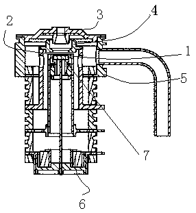
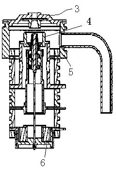
[0021] see figure 1 , Embodiment 1 of the present invention provides a technical solution: a high duty ratio nanomaterial cold cathode electron gun, the shadow grid is arranged on the cold cathode emission surface, the two are at the same potential, the shadow grid is a planar spoke grid, The planar cathode and the planar spoke grid are packaged on the cold cathode support assembly in sequence, the planar spoke grid is close to the cold cathode emission surface, shielding part of the cold cathode emission area, and laser spot welding is used between it and the cold cathode support of the cold cathode support assembly welding.

[0022] The control grid is also a planar spoke control grid, and the control grid is packaged on the cold cathode support assembly, and the control grid and the shadow grid plane spoke grid are grid-matched, and then the control grid is connected between the control grid and the control grid support of the cold cathode support assembly. Laser spot weld...

Embodiment 2

[0024] In the cold cathode electron gun described in Embodiment 2, the shadow grid is etched on the substrate, and nanomaterials capable of emitting electrons are arranged in the grid of the shadow grid; a mask is attached to a substrate such as silicon, and the concave hole is etched. Groove, form a grid, clean and remove the mask; attach iron and other catalysts required for the growth of nanomaterials on the substrate; physically polish the substrate to remove the catalyst on the substrate grid; grow nanomaterials on the substrate to obtain a shadow grid cold cathode ; Next, except that the shadow grid is no longer assembled, the others are the same as the first embodiment.

Embodiment 3

[0026] In the cold-cathode electron gun described in the third embodiment, the shadow grid and the control grid are conical pillar grids, and the others are the same as in the first embodiment.


PUM


Abstract

The invention relates to a high-working-ratio nano material cold cathode electron gun, which comprises a focusing electrode, an anode, a cathode, a shadow grid and a control grid, the shadow grid is arranged on a cold cathode emission surface, the shadow grid and the cold cathode emission surface are in an equipotential state, and the shadow grid is prepared from a metal material or a semiconductor material; and the control grid is arranged right in front of the shadow grid at a preset distance, the shape of the control grid is similar to that of the shadow grid, and the shadow grid and the control grid are arranged opposite to each other and are arranged opposite to the cathode emission surface. According to the cold cathode electron gun adopting the technical scheme, electron bombardmentof the control grid is avoided, the problem that the control grid is burnt is solved, the problem that the cold cathode electron gun only can work in a small working ratio state is solved, the application of a nano material cold cathode electron gun in an electric vacuum device is expanded, and even development of rapid starting of an electronic system is promoted The cold cathode electron gun has the characteristics of simple structure and convenience in assembly.

Description

technical field [0001] The invention relates to an electric vacuum device, in particular to a high working ratio nano material cold cathode electron gun. Background technique [0002] Traditional linear injection microwave tubes, such as klystrons and traveling wave tubes, are important electronic devices in electronic systems such as microwave relay communications, radar, electronic countermeasures, and satellite communications. The electron gun is the heart of the linear injection microwave tube, which provides the electron beam required for the interaction of the high frequency circuit of the microwave tube. In the field of engineering, electron guns generally use hot cathodes as electron injection emitters, and the warm-up time of hot cathodes usually takes tens to hundreds of seconds. Part of the electron gun adopts the shadow grid and control grid loading technology to increase the switching frequency of the microwave tube. The shadow grid is suspended above the hot c...

Claims


Application Information

Patent Timeline
Patent Type & Authority Applications(China)
IPC IPC(8): H01J29/48H01J29/51B82Y30/00
CPCB82Y30/00H01J29/481H01J29/485H01J29/51
Inventor 曾葆青姜芮芮陈涛刘凯赵伯妃
Owner 中山科立特光电科技有限公司
Why Eureka
Try Eureka