Method for removing sulfur oxides and/or nitrogen oxides from flue gas
A technology of nitrogen oxides and sulfur oxides is applied in the field of removing pollutants in industrial flue gas and removing sulfur oxides and/or nitrogen oxides in industrial flue gas, which can solve the problem of not reaching the standard emission targets, Corrosion hazards, secondary pollution and other problems, to achieve the effect of improving utilization, high removal rate, and sufficient gas-solid contact
- Summary
- Abstract
- Description
- Claims
- Application Information
AI Technical Summary
Problems solved by technology
Method used
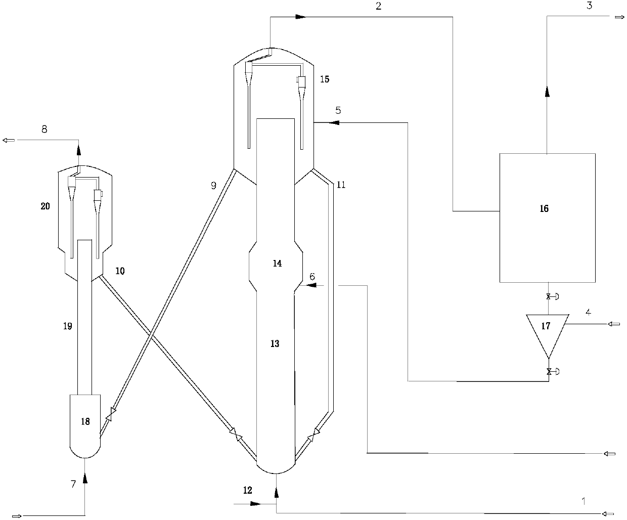
Image

Examples
Embodiment 1-6
[0070] The device and method are the same as in Comparative Example 1, and the composition of raw flue gas is the same as in Comparative Example 1, but ammonia gas is injected into the riser reactor for flue gas treatment, the injection position is at the upper part of the flue gas inlet 500mm, and the amount of ammonia gas is 2ml / min; Flue gas treatment was carried out at normal pressure, 300°C, 400°C, 500°C, 600°C, and 650°C;
Embodiment 7-12
[0076] The device and method are the same as in Comparative Example 7, and the composition of raw flue gas is the same as in Comparative Example 1, but inject ammonia into the flue gas treatment reactor, the injection position is in the lower part of the bed section, and the ammonia consumption is 2ml / min; Flue gas treatment was carried out at 300°C, 400°C, 500°C, 600°C, and 650°C; the catalyst regeneration method and conditions were the same as in Comparative Example 1. The test results are shown in Table 3.
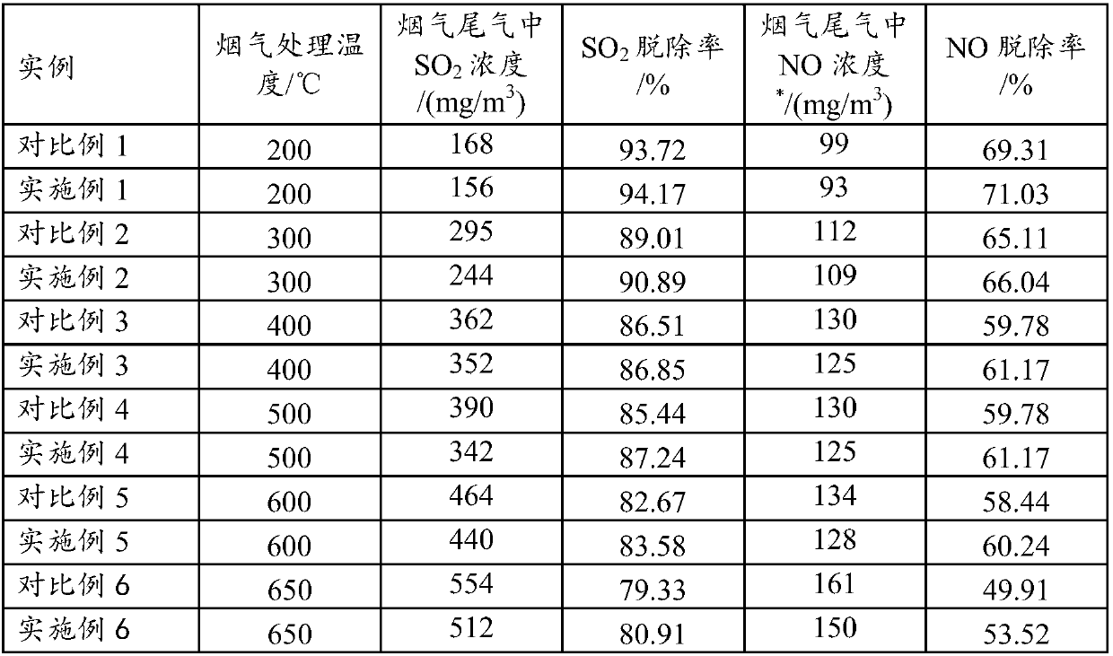
[0077] It can be seen from the data in Table 2 and Table 3: For the flue gas treatment-catalyst regeneration process in the continuous circulation mode, for the flue gas treatment part, the combination of riser and bed layer is better than the single riser method; After passing a small amount of reducing medium ammonia into the treatment reactor, the NO x removal effect.
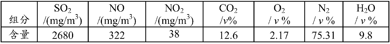
[0078] Table 1
[0079]
[0080] Table 2
[0081]
[0082] *Note: No NO was detected in f...
PUM
| Property | Measurement | Unit |
|---|---|---|
| Packing density | aaaaa | aaaaa |
| Packing density | aaaaa | aaaaa |
| Packing density | aaaaa | aaaaa |
Abstract
Description
Claims
Application Information
 - R&D
- Intellectual Property
- Life Sciences
- Materials
- Tech Scout
- Unparalleled Data Quality
- Higher Quality Content
- 60% Fewer Hallucinations
Browse by: Latest US Patents, China's latest patents, Technical Efficacy Thesaurus, Application Domain, Technology Topic, Popular Technical Reports.
© 2025 PatSnap. All rights reserved.Legal|Privacy policy|Modern Slavery Act Transparency Statement|Sitemap|About US| Contact US: help@patsnap.com