Electrochemical treatment method and device of carbon particles

A processing device and technology for carbon particles, which are applied in chemical instruments and methods, inorganic chemistry, fiber processing, etc., can solve the problems of grafting method that does not meet environmental protection standards, strong corrosiveness of equipment, etc., and achieve environmental friendliness, low cost, The effect of easy availability of raw materials

Active Publication Date: 2019-04-23
SHANXI INST OF COAL CHEM CHINESE ACAD OF SCI
View PDF5 Cites 2 Cited by
  • Summary
  • Abstract
  • Description
  • Claims
  • Application Information

AI Technical Summary

Problems solved by technology

[0004] The purpose of the present invention is to solve the technical problems of the existing acid oxidation method for treating carbon particles, which are highly corrosive to equipment and the grafting method does not meet the environmental protection standards. The present invention provides a low-cost, simple operation and suitable for industrialization. Method and device for chemically treating carbon particles to obtain carbon particles with rich surface functional groups

Method used


Image

  • Electrochemical treatment method and device of carbon particles
  • Electrochemical treatment method and device of carbon particles
  • Electrochemical treatment method and device of carbon particles

Examples


Embodiment 1

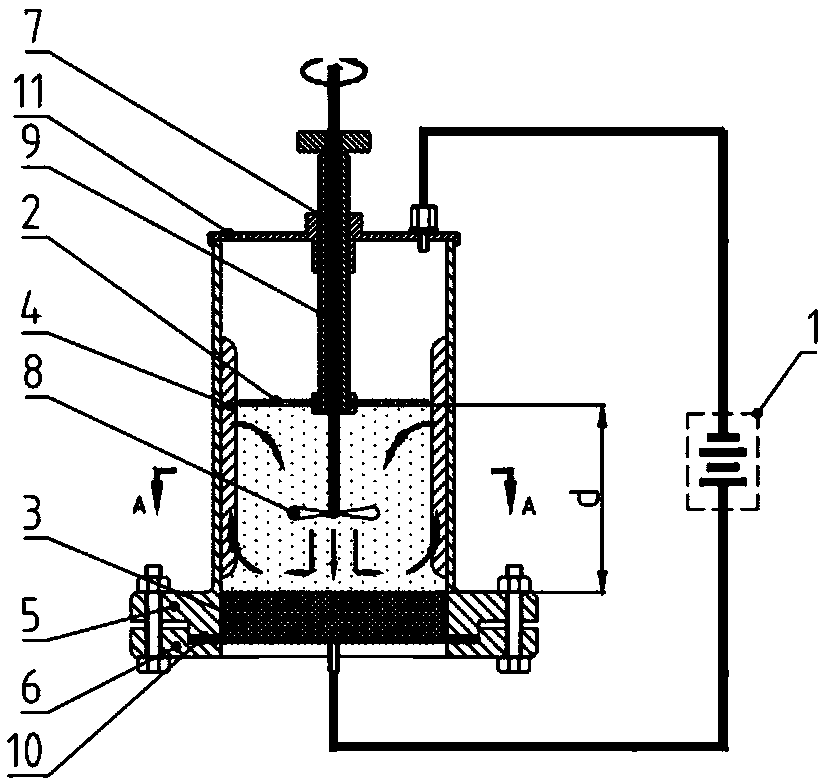
[0049] Such as Figure 2-4 As shown, a device for electrochemically treating carbon particles in this embodiment includes a power supply 1, a copper cathode plate 2, a graphite anode plate 3, and 4 separator columns 4 with a rectangular cross section (that is, θ is 90°). , the reactor shell 5, the base 6, the stirring rod 7, the stirring blade 8, the pole plate distance adjustment screw 9, the sealing ring 10 and the reactor cover plate 11, and the reactor shell 5 and the base 6 are connected by a flange , the reactor cover plate 11 is arranged on the upper port of the reactor housing 5, the anode plate 3 is arranged at the connection between the reactor housing 5 and the base 6, and is sealed by a sealing ring 10, and the pole plate distance adjustment screw rod 9 and The screw hole provided in the middle of the reactor cover plate 11 is threadedly connected, the cathode plate 2 is arranged at the lower end of the pole plate distance adjusting screw 9, and the pole plate dist...

Embodiment 2~3

[0056] The device for electrochemically treating carbon particles with the same structure as in Example 1 is adopted, and the design of the separator column and the electrode plate are changed: the front bottom angle θ of the cross section of the separator column (4) whose cross section is rectangular (that is, θ is 90°) The angle can be adjusted in the range of 0.1-90°; the anode plate can be an inert material electrode such as gold electrode, platinum electrode or graphite electrode, and the cathode plate can be any iron electrode, copper electrode, aluminum electrode, gold electrode, platinum electrode or graphite electrode. Electrode; specific angle design and plate material are listed in Table 1.

[0057] Use the same method for electrochemically treating carbon particles as in Example 1, change the electrode material carbon particle type, electrolyte type and concentration, processing voltage, processing time, stirring mode, and carry out electrochemical processing. After...

Embodiment 4~6

[0059] The device for electrochemically treating carbon particles with the same structure as in Example 1 is adopted, and the design of the separator column and the electrode plate are changed: the front bottom angle θ of the cross section of the separator column (4) whose cross section is rectangular (that is, θ is 90°) The angle can be adjusted in the range of 0.1-90°; the anode plate can be an inert material electrode such as gold electrode, platinum electrode or graphite electrode, and the cathode plate can be any iron electrode, copper electrode, aluminum electrode, gold electrode, platinum electrode or graphite electrode. Electrode; specific angle design and plate material are listed in Table 1.

[0060] Use the same method for electrochemically treating carbon particles as in Example 1, use a DC stabilized power supply to process the carbon particles in a constant current mode, change the type of electrode material carbon particles, the type and concentration of the elec...


PUM

PropertyMeasurementUnit
particle diameteraaaaaaaaaa

Abstract

The invention provides an electrochemical treatment method and device of carbon particles and mainly solves the technical problem that an existing acid oxidation process to treat carbon particles causes great corrosion on equipment and a grafting process fails to meet the environmental protection standard. A carbon particle suspension is placed between an anode and a cathode which are parallel andspaced; a constant voltage is applied between the cathode and the anode by an electrochemical method; by introducing current of constant strength or by means of cyclic voltammetry, the carbon particles are brought to contact with the surface of the anode, and oxygen-bearing nitrogen-bearing functional groups are generated by reacting. The method provided herein as a carbon particle surface treatment method, has the advantages that the raw material is easy to obtain, the cost is low, operation is simple, and large-scale preparation is available; the type, quantity and distribution of the functional groups are controllable.

Description

technical field [0001] The invention belongs to the technical field of electrochemical treatment, and also belongs to the processing field of carbon particle materials. Background technique [0002] Carbon particles refer to carbon materials including carbon black, carbon nanotubes, carbon nanofibers, chopped carbon fibers, graphene, carbon quantum dots, and the like. Generally, carbon particles have excellent mechanical, electrical and thermal properties, and can be used as coating additives, fillers or reinforcing materials for composite materials. However, generally speaking, the surface of carbon particles is inert, with high specific surface energy and poor affinity with matrix materials, which seriously affects the application of carbon particles in coatings, composite materials and other fields. How to properly treat the surface of carbon particles, so that the surface of carbon particles has certain active functional groups, is of great significance for giving full ...

Claims


Application Information

Patent Timeline
Patent Type & Authority Applications(China)
IPC IPC(8): C01B32/168C01B32/194C01B32/198C01B32/156C01B32/15D06M10/06D06M10/08D06M13/51D06M11/55D06M11/70D06M11/38D06M11/76D06M11/56C25D11/02C25D7/00C09C1/56C09C3/04D06M101/40
CPCC01B32/15C01B32/156C01B32/168C01B32/194C01B32/198C09C1/56C09C3/04C25D7/00C25D11/02D06M10/06D06M10/08D06M11/38D06M11/55D06M11/56D06M11/70D06M11/76D06M13/51D06M2101/40
Inventor 吴刚平刘玉婷张巍松李文君
Owner SHANXI INST OF COAL CHEM CHINESE ACAD OF SCI
Why Eureka
Try Eureka