Multi-stage solid particle heat absorber for tower type solar thermal power generation

A technology of tower solar energy and solid particles, which is applied in solar thermal power generation, solar collectors, solar heat storage, etc., can solve problems such as thermal stress damage, wear on the inner wall of metal pipes, and excessive falling speed of particles, and achieve uniform energy Fluid density distribution, avoiding local overheating, and reducing the effect of temperature differences

Active Publication Date: 2019-04-23
INST OF ELECTRICAL ENG CHINESE ACAD OF SCI
View PDF10 Cites 8 Cited by
  • Summary
  • Abstract
  • Description
  • Claims
  • Application Information

AI Technical Summary

Problems solved by technology

However, this patent utilizes the indirect heat absorption and heat exchange of the metal tube, which is the same as the traditional molten salt heat absorber, and also has the problems of thermal stress damage and local hot spots being melted after the metal tube is heated unevenly. Due to the disordered flow of solid particles in the tube, it is easy to cause wear on the inner wall of the metal tube and affect the service life of the metal tube
U.S. Patent US8109265 discloses a free-falling particle heat absorber that circulates air in the heat-absorbing cavity, which can effectively reduce heat loss. The disadvantage is that the falling speed of the particles is too fast and the temperature rise of the particles is not high
Chinese patent CN106524541A discloses a solid particle heat absorber in which dense ceramic particles fall in a vertical or incli

Method used


Image

  • Multi-stage solid particle heat absorber for tower type solar thermal power generation
  • Multi-stage solid particle heat absorber for tower type solar thermal power generation
  • Multi-stage solid particle heat absorber for tower type solar thermal power generation

Examples


Embodiment Construction

[0057] The present invention will be further described below in conjunction with the accompanying drawings and specific embodiments.

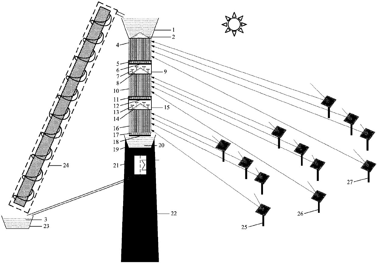
[0058] Such as figure 1 As shown, the solid particle heat absorber of the present invention includes a particle distributor 1, a first conical reforming fluid 2, solid particles 3, a first heat absorption section 4, a second heat absorption section 10, and a third heat absorption section 16. High-temperature solid particle storage tank 19, particle heat exchanger 21, heat absorption tower 22, low-temperature solid particle storage tank 23, screw elevator 24, first-stage particle mixing chamber 9, second-stage particle mixing chamber 15, third-stage particle mixing chamber The first-stage conical funnel 17 and the third-stage flow regulating mechanism 18, the inner ring heliostat field 25, the middle ring heliostat field 26, and the outer ring heliostat field 27. A first conical reforming body 2 is placed in the particle distributor 1 at its bo...


PUM


Abstract

A multi-stage solid particle heat absorber for solar thermal power generation is characterized in that heliostat fields (25, 26, 27) are used for correspondingly supplying radiation energy to a third-stage heat absorbing section (16), a second-stage heat absorbing section (10) and a first-stage heat absorbing section (4) which are annularly arranged at the upper part of a heat absorbing tower (22); low-temperature solid particles (3) in a low-temperature solid particle storing tank (23) are conveyed to a particle distributor (1) through a spiral lifting machine (24); the low-temperature solidparticles (3) flow into the first-stage heat absorbing section (4) for heating under the flow guide effect of a tapered insert (2) at the bottom part of the particle distributor (1); the heated low-temperature solid particles (3) enter a first-stage particle mixing chamber (9) and then enter the heat absorbing section at the next stage after temperature equalization; the low-temperature solid particles (3) flow into a high-temperature solid particle storing tank (20) through a tapered funnel (17) under the effect of a final-stage flow rate adjusting mechanism (18); after transferring heat to apower generation working medium, high-temperature solid particles (19) are transformed into the low-temperature solid particles (3) and then flow into the low-temperature solid particle storing tank(23).

Description

technical field [0001] The invention relates to a solid particle heat absorber. Background technique [0002] The large-scale heat storage system in the solar thermal power station can provide the heat required for the system to continue to generate electricity when the sun is insufficient, such as rain, cloud cover, and sunset, effectively extending the operating time of the power station. The heat storage system also enables the solar thermal power station to provide reliable power to the grid stably and safely, and its energy storage cost is low, only 1 / 30 of the cost of large-scale battery energy storage. Molten salt has been widely used in Solar Two, Andasol, Gemasolar and other power stations as an endothermic working fluid and heat storage medium at the same time, but it needs to be equipped with an electric heating system to prevent the molten salt from solidifying, and the working temperature cannot be lower than 290 °C. In order to prevent pyrolysis of molten salt...

Claims


Application Information

Patent Timeline
IPC IPC(8): F24S23/70F24S60/10F24S80/30F24S10/70
CPCY02E10/44
Inventor 聂辅亮白凤武王志峰
Owner INST OF ELECTRICAL ENG CHINESE ACAD OF SCI
Why Eureka
Try Eureka