Split type laser focusing device

A focusing device and split-type technology, applied in laser welding equipment, metal processing equipment, welding equipment, etc., can solve the problem of high processing precision, complex spherical aberration lens design and processing technology, and limited direct application of axicon method and promotion issues, to achieve the effect of high energy utilization and improve the quality of imaging focus

Pending Publication Date: 2019-04-26
江苏先河激光研究院有限公司 +1
View PDF0 Cites 5 Cited by
  • Summary
  • Abstract
  • Description
  • Claims
  • Application Information

AI Technical Summary

Problems solved by technology

Comparing the above several methods, each has advantages and disadvantages: the annular slit-lens method has a simple structure and is easy to implement, but the energy utilization rate of the incident light is low; the computational holography method is also relatively simple in structure, but has a higher quality for the hologram. Requirements; the structure of the spherical aberration lens method is relatively flexible, but the design and processing technology of the spherical aberration lens are complicated, and the size and light intensity of the center spot will change with the position; the axicon method has a simple structure and can produce high-quality Bessel The energy utilization rate of the light beam is greatly improved compared with the annular slit-lens method. It is the mainstream method of laser micromachining at present, and the axicon method has higher requirements on the processing accuracy of the axicon. The actual depth of laser micromachining is generally several hundred microns. To the order of several millimeters, a ring-shaped spot is required at the cone surface corresponding to the incident axis. Although the power utilization rate is much higher than that of the annular slit-lens method, it still needs to block a large amount of laser energy. Although the center spot size can be kept fixed, the light The strength will change with the location, and there may be severe vibrations, figure 1 The on-axis light intensity distribution curve of the plane wave passing through the axicon mirror provided by the prior art axicon mirror method, the above-mentioned shortcomings limit the direct application and promotion of the axicon mirror method in laser micromachining

Method used


Image

  • Split type laser focusing device
  • Split type laser focusing device
  • Split type laser focusing device

Examples


Embodiment 1

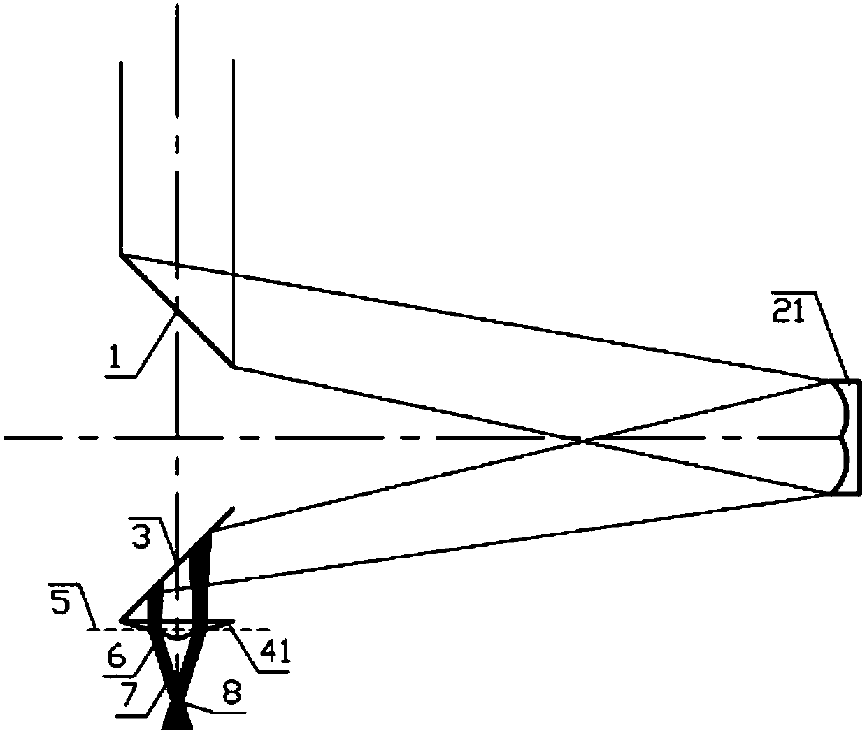
[0057] see figure 2 , the structural diagram of the laser focusing device provided by the first embodiment of the present invention is as follows figure 2 As shown, the laser focusing device is composed of a first reflector, a concave reflector with an annular arc-shaped concave surface, a third reflector, and a conical mirror. The first reflector and the third reflector are both plane reflectors. After being reflected by the first reflector, the incident laser beam is incident on the concave reflector with circular arc-shaped concave surface at a small angle, reflected by the concave reflector with circular arc-shaped concave surface, and then reflected by the third reflector, It enters the conical mirror and exits from the side of the cone. According to the beam focusing requirements, calculate the light field distribution range in the focusing device, calculate the base angle of the processed cone, match the refractive index of the cone material, process the cone accordi...

Embodiment 2

[0071] The structural schematic diagram of the laser focusing device provided by the second embodiment of the present invention is as follows: Figure 13 As shown, the laser focusing device is composed of a first reflector, an equivalent Fresnel reflector, a third reflector, and a circular table mirror, and the first reflector and the third reflector are both plane reflectors. After being reflected by the first reflector, the incident laser beam is incident on the equivalent Fresnel reflector at a small angle, reflected by the equivalent Fresnel reflector, and then reflected by the third reflector, enters the circular table mirror, and exits from the side of the circular table . The split-type laser focusing device, according to the beam focusing requirements, calculates the distribution range of the light field in the focusing device, calculates the size of the bottom angle of the processed frustum, matches the refractive index of the material of the frustum, and processes th...

Embodiment 3

[0078] The second reflector is a Fresnel reflector equivalent to a concave reflector having an annular arc-shaped concave surface. Other technical features of this embodiment are the same as those of Embodiment 1. In this example, the second reflector is the equivalent Fresnel reflector of the second embodiment of the present invention. Compared with the concave reflector with circular arc-shaped concave surface of the first embodiment, the equivalent Fresnel reflector The reflector saves more raw materials, is easy to process, and reduces costs. Such as Figure 14 Shown is a structural schematic diagram of the through-center axial section of the equivalent Fresnel reflector of the second embodiment of the present invention, indicating the symmetry of the equivalent Fresnel reflector about the axis. Such as Figure 15 shown as Figure 14 , indicating the rotational symmetry of the equivalent Fresnel mirror about the center of the left view, combined with Figure 14 , the ...


PUM


Abstract

The invention relates to a split type laser focusing device. The split type laser focusing device comprises a first reflecting mirror, a second reflecting mirror, a third reflecting mirror and an output focusing mirror, wherein the reflecting surface of the first reflecting mirror and the reflecting surface of the third reflecting mirror are planes; the reflecting surface of the second reflectingmirror is a ring-shaped circular-arc-shaped concave surface or an equivalent Fresnel surface; the output focusing mirror is equipped with a tapered surface; the first reflecting mirror is used for receiving and reflecting an incoming laser beam to the second reflecting mirror; emergent light of the first reflecting mirror comes into the second reflecting mirror with a small angle; the second reflecting mirror is used for receiving emergent light of the first reflecting mirror and reflecting the emergent light to the third reflecting mirror; the third reflecting mirror is used for receiving emergent light of the second reflecting mirror and reflecting the emergent light to the output focusing mirror; and the output focusing mirror is used for receiving emergent light of the third reflectingmirror, and is emitted by the tapered surface of the output focusing mirror, so that a similar bessel beam is formed. The split type laser focusing device is high in energy utilization rate; and thecenter spot size and light intensity of the output similar bessel beam are basically unchanged within a position focusing range on the axis of the output focusing mirror.

Description

technical field [0001] The invention relates to the field of laser processing, in particular to a split laser focusing device. Background technique [0002] The spot diameter of the Bessel beam can reach the minimum wavelength level and can basically remain unchanged over a long distance. Compared with the Gaussian beam, it has a longer focal depth, so it is very suitable for laser micromachining, especially in It has incomparable advantages in processing materials with large aspect ratio. [0003] The ideal Bessel beam cannot be realized in reality because it occupies infinite space and has infinite energy, but people can obtain approximate Bessel beams through experiments. So far, researchers have proposed many experimental methods for generating Bessel beams, which can be roughly divided into two categories: active and passive. The so-called active type is to directly generate Bessel beams from lasers through a resonant cavity with a specific structure (also called reso...

Claims


Application Information

Patent Timeline
Patent Type & Authority Applications(China)
IPC IPC(8): B23K26/064
CPCB23K26/0643
Inventor 李玫瑰秦应雄张怀智段光前赵侠
Owner 江苏先河激光研究院有限公司
Why Eureka
Try Eureka