
Acid leaching device for fiber yarn rope

A technology of acid leaching and yarn rope, applied in the equipment field of acid leaching process, can solve the problems of low production efficiency, poor quality consistency of high silica glass fiber yarn rope, etc., to improve quality and production efficiency, improve acid The effect of non-uniform temperature rise and quality improvement

Pending Publication Date: 2019-04-26
NANJING FIBERGLASS RES & DESIGN INST CO LTD
View PDF5 Cites 1 Cited by
  • Summary
  • Abstract
  • Description
  • Claims
  • Application Information

AI Technical Summary

Problems solved by technology

[0004] Therefore, the technical problem to be solved by the present invention is to overcome the defects of poor quality consistency and low production efficiency of the high-silica glass fiber rope produced by the acid leaching device in the prior art, thereby providing an acid leaching device

Method used


Image

  • Acid leaching device for fiber yarn rope
  • Acid leaching device for fiber yarn rope
  • Acid leaching device for fiber yarn rope

Examples


Embodiment 1

[0034] Embodiment 1 acid leaching device

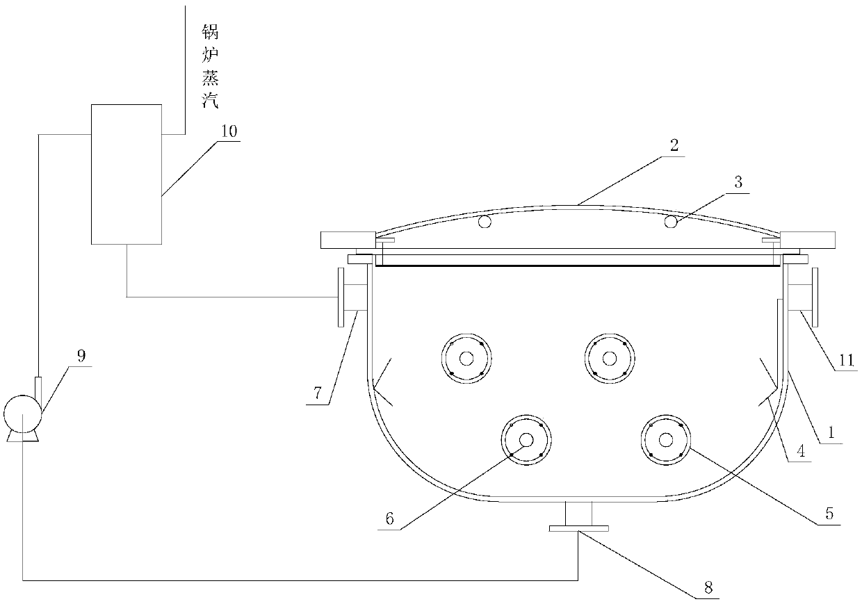
[0035] Such as figure 1A specific embodiment of the acid leaching device shown includes an acid leaching tank 1 and a heat exchange assembly 10, and the acid leaching tank 1 is provided with an acid inlet 7 and an acid outlet 8; wherein, the acid inlet 7 Set on the side wall near the top end of the acid leaching tank 1, the acid outlet 8 is set at the bottom of the acid leaching tank 1, and the opening of the acid leaching tank 1 is provided with a The acid leaching tank cover body 2; the heat exchange assembly 10 is arranged on the outside of the acid leaching tank 1, and is used for heating the acid liquid in the acid outlet 8 and then inputting it into the acid inlet 7 to complete the acid leaching The heating of the acid liquid, the heat exchange assembly 10 is provided with a medium flow channel for the circulation of the heating medium and an acid liquid flow channel for the circulation of the acid liquid, and the outlet of the...

Embodiment 2

[0052] The production technology of embodiment 2 high silica glass fiber yarn rope

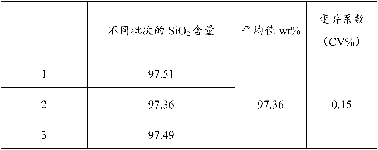
[0053] Acid leaching: wind the ternary sodium borosilicate glass fiber yarn rope (specification: BC8-220S120) on the acid-resistant creel with a winding ratio of 3.14. The radius of the circumscribed circle of the frame is 500cm, and the thickness of the yarn layer of the fiber yarn rope wound is 2.6cm, and then the creel is connected in the acid leaching tank by rotating the shaft; use the hydrochloric acid solution that the equivalent concentration is 3.1N / L as Acid solution, inject the hydrochloric acid solution into an acid-resistant heat exchanger and heat it to 50°C, then inject it into the acid leaching tank; then start the creel to rotate, control the creel rotation speed to 20rpm, and refill the acid solution in the acid leaching tank at the same time It is pumped into the heat exchanger for circulation heating until the temperature of the acid solution is 95°C, and then the temperatu...


PUM


Abstract

The invention relates to equipment for acid leaching technological treatment, in particular to an acid leaching device for a fiber yarn rope. The acid leaching device comprises an acid leaching tank,a yarn carrying assembly, a driving motor and a heat exchange assembly, wherein the acid leaching tank is provided with an acid inlet and an acid outlet; the yarn carrying assembly is positioned inside the acid leaching tank and comprises a rotating shaft and a yarn reeling structure sleeving the rotating shaft; the driving motor is arranged outside the acid leaching tank and is used for driving the rotating shaft to rotate so as to drive the yarn reeling structure to rotate; the heat exchange assembly is arranged outside the acid leaching tank, communicates with the acid inlet and the acid outlet respectively, and is used for heating acid liquid at the acid outlet and then inputting the acid liquid into the acid inlet so as to complete heating of the acid liquid. The acid leaching devicecan increase the content of silicon oxide in a prepared high-silica glass fiber rope, improve the uniformity of a strength variation coefficient and improve the product quality and the production efficiency.

Description

technical field [0001] The invention relates to equipment for acid leaching process, in particular to an acid leaching device for fiber yarn rope. Background technique [0002] With the advancement and development of aerospace science and technology, people's requirements for high-temperature-resistant wave-transparent insulation materials are also increasing. Traditional high-temperature-resistant insulation materials such as asbestos and rock wool can no longer meet high standards due to their high thermal conductivity. requirements. High-silica glass fiber is a kind of high-temperature-resistant inorganic fiber, which has the characteristics of high softening point, low thermal conductivity, and good wave permeability, and has attracted more and more attention. High silica glass fiber is mostly made of alkali-free glass fiber, binary glass fiber or ternary glass fiber through acid leaching, water washing, drying and sintering. The control of acid concentration, treatmen...

Claims


Application Information

Patent Timeline
Patent Type & Authority Applications(China)
IPC IPC(8): C03C25/66
CPCC03C25/66
Inventor 祖群戴尚芹潘坚郭仁贤刘骏
Owner NANJING FIBERGLASS RES & DESIGN INST CO LTD
Learn More