A VOCS waste gas adsorbent desorption pyrolysis process

An adsorbent and desorption technology, used in the petroleum industry, combustible gas purification, combustible gas purification/reconstruction, etc., can solve problems such as leakage, no solution for electrothermal purification filter elements, and VOCs exhaust gas sealing failure, etc., to reduce pollution. effects of emissions

Active Publication Date: 2021-09-21
宋丽 +2
View PDF5 Cites 0 Cited by
  • Summary
  • Abstract
  • Description
  • Claims
  • Application Information

AI Technical Summary

Problems solved by technology

[0003] Existing technology-Aiming at the practical problems of large air volume VOCs waste gas treatment, the technical solution of the electrothermal purification filter element is proposed for the enclosure structure, the air inlet surface, and the air outlet surface with one or more layers of porous sieve plates or adsorption beds filled with sieves. However, there is no solution for how to replace the electrothermal purification filter element in normal production after the adsorption of VOCs exhaust gas is saturated; prior art 2 proposes the use of molecular sieve runners and honeycomb activated carbon runners for VOCs exhaust gas adsorption and desorption for the practical problems of VOCs exhaust gas treatment , Concentration, and combustion technical solutions, it is undoubtedly feasible to use a mechanical runner to solve the technical solution of replacing the adsorbent after the VOCs exhaust gas is saturated, but the sealing problem must be solved for moving equipment such as the runner, especially the rotary The problem of VOCs exhaust gas leakage due to seal failure under continuous production conditions during wheel replacement

Method used


Image

  • A VOCS waste gas adsorbent desorption pyrolysis process
  • A VOCS waste gas adsorbent desorption pyrolysis process
  • A VOCS waste gas adsorbent desorption pyrolysis process

Examples


Embodiment Construction

[0028] The present invention will be further described below in conjunction with the accompanying drawings and specific embodiments.

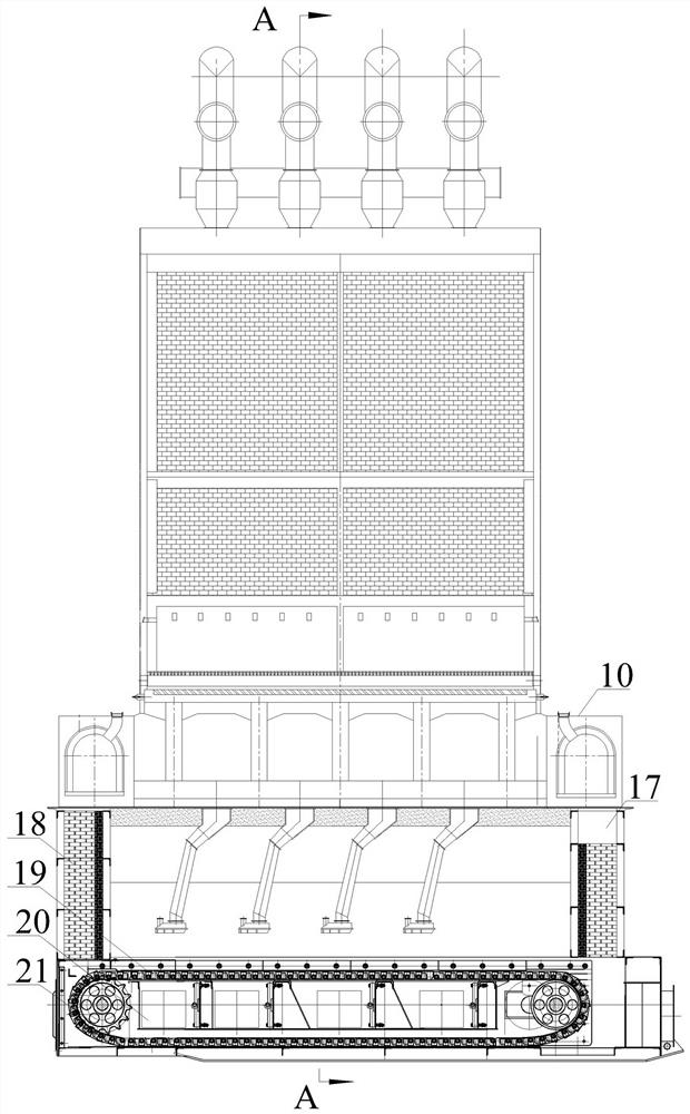
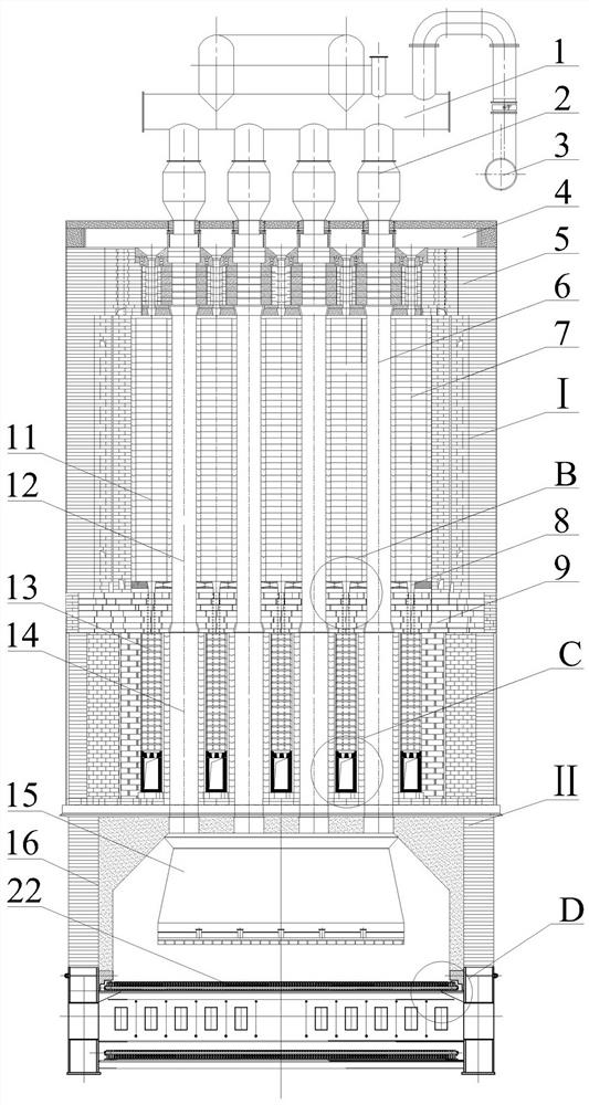
[0029] Such as figure 1 , figure 2 , image 3 , Figure 4 , Figure 5 Shown, a kind of VOCs waste gas adsorbent desorption pyrolysis process is characterized in that:

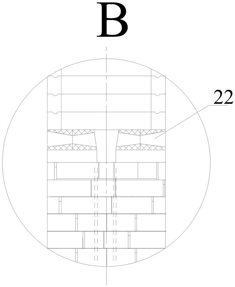
[0030] Step 1: The fire path 7 and the vertical path 6 of the desorption pyrolysis furnace I are built adjacent to each other, and the middle partition arch 9 divides the desorption pyrolysis furnace body 5 into upper and lower areas, namely the upper area, the desorption pyrolysis area, and the lower area In the heat storage area, the fire channel 7 is divided into upper and lower chambers, namely pyrolysis chamber 11 and heat storage chamber 13, and the vertical passage 6 is divided into upper and lower chambers, namely desorption chamber 12 and sealing chamber 14. Pyrolysis chamber 11 is filled with high alumina Ball packing, the particle diameter of high alumina ball p...


PUM

PropertyMeasurementUnit
diameteraaaaaaaaaa
thicknessaaaaaaaaaa

Abstract

The invention relates to the technical field of environmental protection, in particular to a desorption pyrolysis process of a VOCs waste gas adsorbent. Its characteristics are: start the feeding system to feed materials to the vertical channel, the adsorbent moves continuously in the vertical channel from top to bottom under the action of gravity, and the air injection header reuses the tail gas discharged from the fire channel to purge the adsorption in the vertical channel and then mixed with the desorbed VOCs waste gas and sent to the pyrolysis chamber for oxidative pyrolysis through the grate brick at the bottom of the desorption chamber. The excess oxygen in the gas oxidizes and pyrolyzes it, and the tail gas flows into the smoke exhaust header, and the exhaust gas is collected by the air injection header and re-entered into the vertical channel. The return ratio is designed to be 1:10; the air distribution plate will pass through the VOCs exhaust gas The exhaust tail gas treated by the environmental protection purification facility is introduced, and the tail gas flows into the adsorbent that is purged and cooled and paved on the chain-driven grate bed row through the gap between the adjacent grate bed rows, and quickly completes the process of mass transfer and heat transfer with the adsorbent particles, and then Then it is discharged through the smoke outlet of the kiln box.

Description

technical field [0001] The invention relates to the technical field of environmental protection, in particular to a desorption pyrolysis process of a VOCs waste gas adsorbent. Background technique [0002] Gaseous pollutants emitted by industry are the main source of atmospheric environmental pollutants, among which volatile organic compound waste gas (VOCs) is a gaseous pollutant that is seriously harmful to the environment, and it is also an occupational hazard that affects the health of operators in the workplace It is widely derived from chemical industries such as paints, coatings, coatings, lubricants, and rubber. Due to its huge destructive effect on the human body and the natural environment, the country has issued relevant laws and regulations to strictly control its governance and emissions. At present, the commonly used treatment methods of organic waste gas treatment technology include combustion method, chemical oxidation method, chemical absorption method, ads...

Claims


Application Information

Patent Timeline
Patent Type & Authority Patents(China)
IPC IPC(8): B01D53/02B01J20/34B01J20/20B01J20/18
Inventor 宋丽师明王红云杨松
Owner 宋丽
Why Eureka
Try Eureka