
Porous stent for bone repair and preparation method thereof

A porous scaffold and bone repair technology, applied in the direction of bone implants, additive processing, etc., can solve the problems of insufficient bearing capacity, unfavorable time control, complicated design process, etc., to reduce the overall deformation and damage, and increase the deformability. range, the effect of avoiding breakage problems

Active Publication Date: 2019-05-17
SOUTH CHINA INST OF COLLABORATIVE INNOVATION
View PDF14 Cites 5 Cited by
  • Summary
  • Abstract
  • Description
  • Claims
  • Application Information

AI Technical Summary

Problems solved by technology

The structure described in the Chinese patent CN 107847327 A publication is a regular tetrahedral diamond lattice structure, but its structure is relatively complex, the edge length is long, and the strength is low, which cannot meet the two-way requirements of porosity and strength at the same time
The unit structure described in the Chinese patent CN107174382 A is a body-centered cubic lattice structure, and the specific strength value is not indicated in the patent. Referring to its design method, after comparison of tests, it is found that its strength is only 39.04MPa, which is far lower than that of Natural bone tissue compressive strength 100-230MPa
The porous scaffold described in Chinese patent CN108601662 A is an irregular structure. Although the structure is closer to the structure of human bone tissue, the design process is relatively complicated and time-consuming, which is not conducive to time control in traumatic bone repair.
The mechanical properties of the above-mentioned structural unit scaffolds can match the natural bone tissue within a certain range to achieve the purpose of promoting bone growth, but the longer rib length leads to lower overall structural strength and insufficient bearing capacity, thereby limiting the growth microenvironment of bone cells. Affects bone tissue integration

Method used


Image

  • Porous stent for bone repair and preparation method thereof
  • Porous stent for bone repair and preparation method thereof
  • Porous stent for bone repair and preparation method thereof

Examples


Embodiment 1

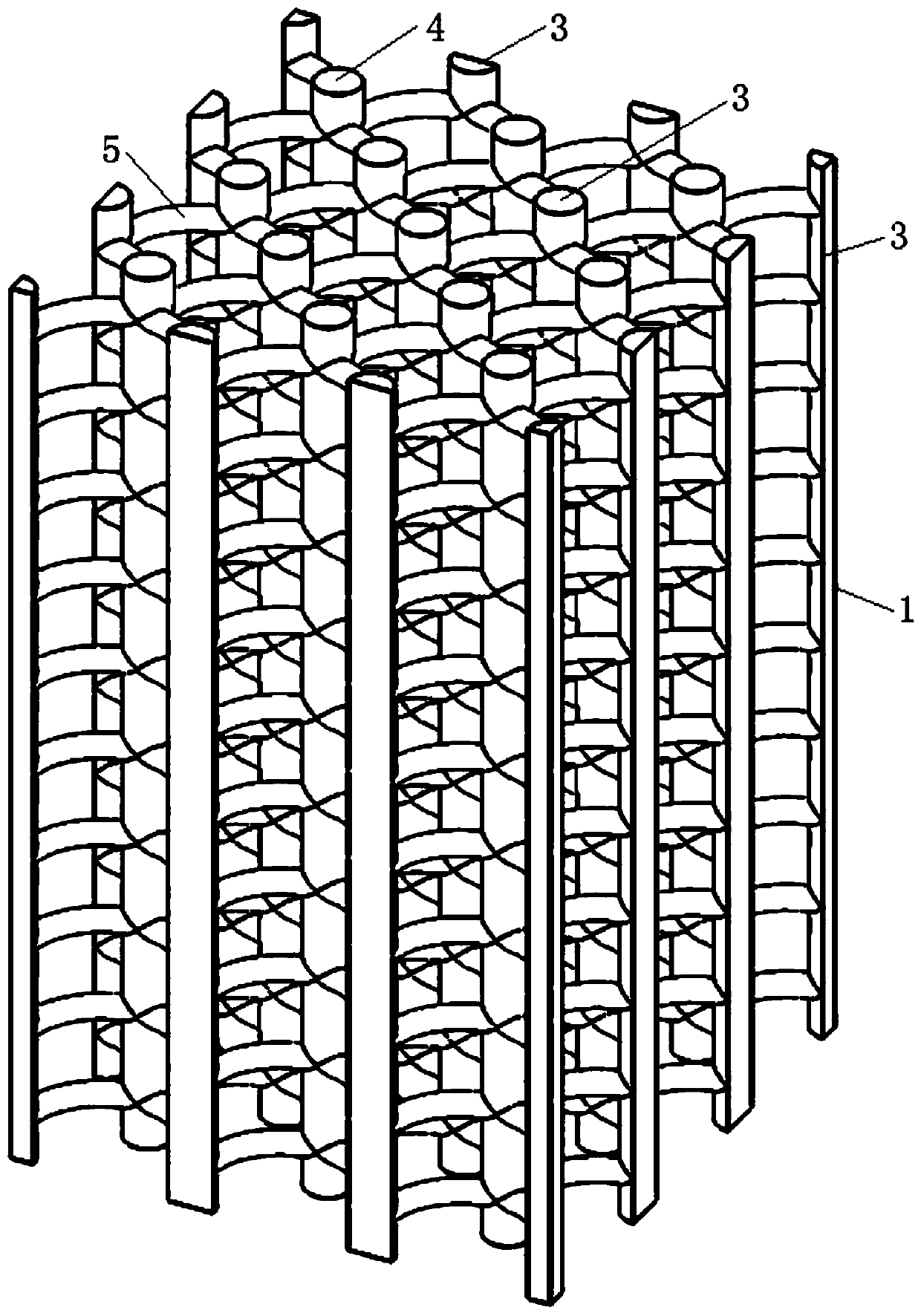
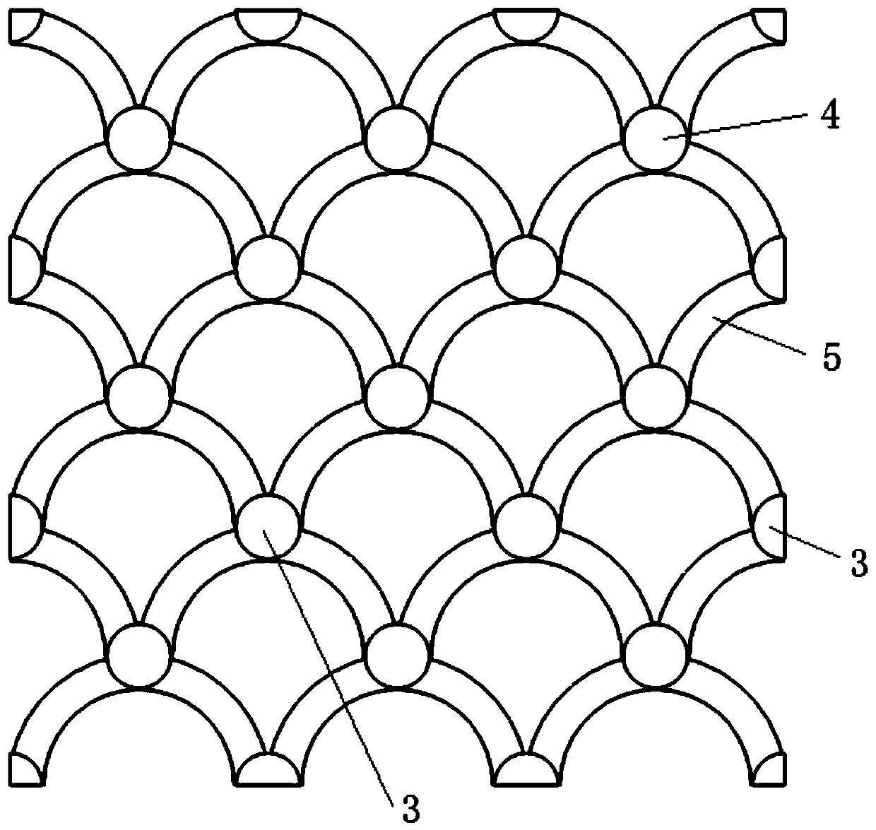
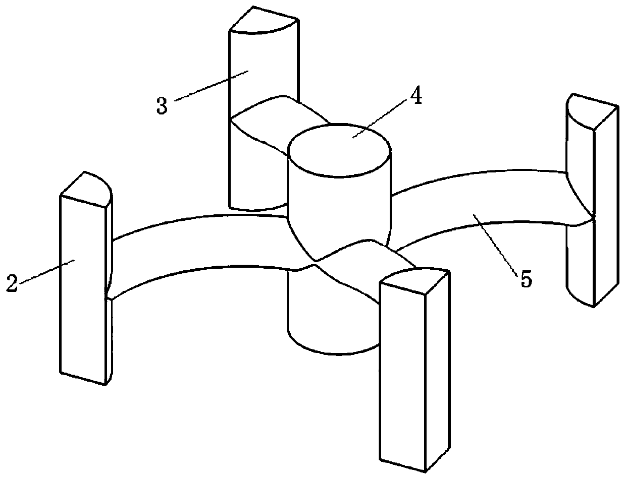
[0040] like Figure 1-Figure 5 The shown porous scaffold for bone repair includes several structural units 2. The outer contour of the structural units 2 is in the shape of a regular square prism. The length of the bottom surface of the regular square prism is a, and the height of the side edges is h. 2 includes a support beam column 3, a central beam column 4 and a connecting rod 5, the support beam column 3 is respectively arranged at the four side edges of the regular square prism, the central beam column 4 is arranged at the center of the regular square prism, and The columns 3 are parallel and equal in height, and a connecting rod 5 is correspondingly arranged between the supporting beam column 3 and the central beam column 4, and the section radii of the supporting beam column 3 and the central beam column 4 are both R, wherein, R≥0.5mm Several structural units 2 are arrayed continuously to form a porous support 1, wherein the support beams and columns 3 between the stru...

Embodiment 2

[0055] This embodiment is the same as embodiment 1 except the following technical features:

[0056] Pure titanium powder was processed by selective laser sintering using an EOS M280 metal printer, and a porous scaffold 1 with a design porosity of 60% was printed, and a compression test was performed using a universal mechanical testing machine. Its compressive strength is 130MPa, and its elastic modulus is 6.05GPa. It can be seen that both the compressive strength and elastic modulus match the natural bone.

Embodiment 3

[0058] This embodiment is the same as embodiment 1 except the following technical features:

[0059] EOS M280 metal printer was used for selective laser sintering to process cobalt-chromium alloy powder, and a porous scaffold 1 with a design porosity of 70% was printed, and a universal mechanical testing machine was used for compression testing. Its compressive strength is 301MPa, and its elastic modulus is 12.85GPa. The porosity of the porous scaffold 1 can be adjusted to meet the needs of different patients.


PUM

PropertyMeasurementUnit
compressive strengthaaaaaaaaaa
elastic modulusaaaaaaaaaa

Abstract

The invention relates to the technical field of medical device design, and discloses a porous stent for bone repair. The porous stent comprises a plurality of structural units; the outer contour of each structural unit is in a regular quadrangular prism shape, the bottom side length of the regular quadrangular prism is a, and the height is h; each structural unit comprises supporting beam columns,a central beam column and connecting rods, wherein the supporting beam columns are arranged at the four side edges of the regular quadrangular prism respectively, the central beam column is arrangedat the center of the regular quadrangular prism and is parallel to and flush with the supporting beam columns, the connecting rods are correspondingly arranged between the supporting beam columns andthe central beam column, and the cross-sectional radius of the supporting beam columns and the cross-sectional radius of the central beam column are both R; the structural units are arrayed to form the porous stent. The invention also provides a preparation method of the porous stent for bone repair. The porous stent has the advantages of high porosity, low elasticity modulus, high bearing capacity and the like.

Description

technical field [0001] The invention relates to the technical field of medical device design, in particular to a porous bracket for bone repair and a preparation method thereof. Background technique [0002] Implant repair is the most advantageous repair method in the repair of large-area bone defects caused by trauma or disease. For example, in a comminuted fracture of the femur, the required implant needs to have a low elastic modulus to match the autogenous bone to prevent stress shielding, and at the same time have a certain bearing capacity to prevent the implant from breaking. Metal porous implants can meet the above requirements and have good biocompatibility. [0003] Among existing products, titanium alloy implants have absolute advantages because of their excellent mechanical compatibility and biological compatibility. The elastic modulus of titanium alloy is closer to that of natural bone tissue than other metals, and there are no or few pathogenic elements in t...

Claims


Application Information

Patent Timeline
Patent Type & Authority Applications(China)
IPC IPC(8): A61F2/28B22F3/105B22F5/00B33Y10/00B33Y80/00
Inventor 郑华德刘丽丽张明
Owner SOUTH CHINA INST OF COLLABORATIVE INNOVATION
Learn More