Porous composite membrane and preparation method thereof, and lithium ion battery comprising porous composite membrane

A composite diaphragm and diaphragm technology, applied in secondary batteries, battery components, circuits, etc., can solve problems such as low electrolyte adsorption rate, high density, and increased battery internal resistance

Inactive Publication Date: 2019-06-07
中材锂膜(常德)有限公司 +1
View PDF0 Cites 1 Cited by
  • Summary
  • Abstract
  • Description
  • Claims
  • Application Information

AI Technical Summary

Problems solved by technology

In order to improve the performance of the diaphragm, the existing technology mainly uses inorganic materials such as aluminum oxide to coat the diaphragm. However, since the coating is made of solid particles, the density is relatively high and the specific surface area is limited, which affects the electrolyte. The low adsorption rate increases the internal resistance of the battery and reduces the battery capacity, especially after multiple cycles. At the same time, coating the solid particles will block the pores on the surface of the diaphragm, resulting in a change in the overall specific surface area of ​​the diaphragm. Small, reducing battery energy density

Method used


Image

  • Porous composite membrane and preparation method thereof, and lithium ion battery comprising porous composite membrane

Examples


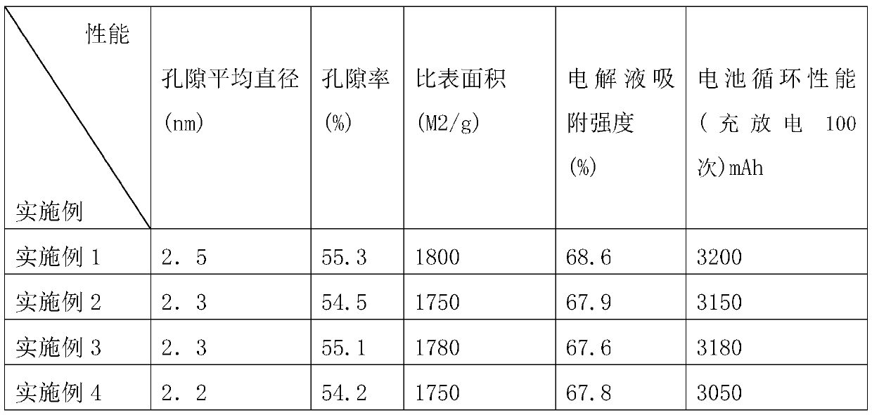
Embodiment 1

[0043] 1.5 g of amine bicarbonate was added to 60 g of polyvinylidene fluoride solution and stirred until dissolved, then 140 g of zirconia powder was added and stirred uniformly to form a slurry. The slurry was applied to one side of the polypropylene separator using a coater to obtain a coating. The coated separator was dried for 1 hour in an oven provided with 4 successive drying sections with increasing temperature (45°C, 55°C, 60°C, 75°C in sequence) to obtain a composite separator.

[0044] The above-mentioned composite diaphragm, nickel-cobalt lithium manganese oxide positive electrode, silicon carbon negative electrode and lithium hexafluorophosphate electrolyte are assembled into a lithium-ion battery in a conventional manner.

Embodiment 2

[0046] 4 g of oxalic acid was added to 20 g of polyvinylidene fluoride solution and stirred until dissolved, then 180 g of nickel oxide powder was added and stirred uniformly to form a slurry. The slurry was applied to one side of the polypropylene separator using a coater to obtain a coating. The coated separator was dried for 1 hour in an oven provided with 4 successive drying sections with increasing temperature (45°C, 55°C, 60°C, 75°C in sequence) to obtain a composite separator.

[0047] The above-mentioned composite diaphragm, nickel-cobalt lithium manganese oxide positive electrode, silicon carbon negative electrode and lithium hexafluorophosphate electrolyte are assembled into a lithium-ion battery in a conventional manner.

Embodiment 3

[0049] 2.5 g of ammonium carbonate was added to 20 g of polyvinylidene fluoride solution and stirred until dissolved, then 180 g of copper oxide powder was added and stirred uniformly to form a slurry. The slurry was applied to one side of the polypropylene separator using a coater to obtain a coating. The coated separator was dried for 1 hour in an oven provided with 4 successive drying sections with increasing temperature (45°C, 55°C, 60°C, 75°C in sequence) to obtain a composite separator.

[0050] The above-mentioned composite diaphragm, nickel-cobalt lithium manganese oxide positive electrode, silicon carbon negative electrode and lithium hexafluorophosphate electrolyte are assembled into a lithium-ion battery in a conventional manner.


PUM

PropertyMeasurementUnit
The average diameteraaaaaaaaaa
Specific surface areaaaaaaaaaaa

Abstract

The present invention provides a porous composite membrane having an excellent specific surface area and capable of providing an excellent electrolyte adsorption strength and a battery cycle performance, and a preparation method thereof and a lithium ion battery comprising a porous composite membrane. The porous composite membrane comprises a polymer membrane and at least one porous coating of thepolymer membrane, the at least one porous coating comprises ceramic powder and a binder as components, nanometer pores with average diameters in a range of 1-5nm are distributed in the at least one porous coating, and the at least one porous coating has the specific surface area in a range of 1200-2000 m2 / g.

Description

technical field [0001] The invention belongs to the technical field of lithium ion batteries, and in particular relates to a porous composite diaphragm, a preparation method thereof and a lithium ion battery containing the same. Background technique [0002] Due to the advantages of high specific energy, long cycle life, and fast charging and discharging, lithium-ion batteries have a wide range of application prospects, such as automobiles, mobile phones, computers, cameras, etc. Lithium-ion batteries include positive and negative electrode materials, electrolytes, and separators. The separator is one of the key components of lithium-ion batteries, which determines the interface structure of the battery and directly affects the capacity, safety performance and cycle performance of the battery. In order to improve the performance of the diaphragm, the existing technology mainly uses inorganic materials such as aluminum oxide to coat the diaphragm. However, since the coating ...

Claims


Application Information

Patent Timeline
IPC IPC(8): H01M2/14H01M2/16H01M2/18H01M10/0525
CPCY02E60/10
Inventor 高保清陈红辉舒均国陈立新杨天乐毛冬琪
Owner 中材锂膜(常德)有限公司
Why Eureka
Try Eureka