Gas arc discharge device, coupling system connected to vacuum cavity and ion nitriding process

An arc discharge and vacuum cavity technology, applied in metal material coating process, coating, solid diffusion coating and other directions, can solve the problems of high nitriding efficiency, low nitriding efficiency, deep nitriding layer, etc. The effect of high nitrogen efficiency, good uniformity and deep nitriding layer

Pending Publication Date: 2019-06-28
泰安东大新材表面技术有限公司 +1
View PDF2 Cites 4 Cited by
  • Summary
  • Abstract
  • Description
  • Claims
  • Application Information

AI Technical Summary

Problems solved by technology

The nitriding layer prepared by this method has good uniformity, high nitriding efficiency, and deep nitriding layer, which overcomes the workpiece burn caused by the

Method used


Image

  • Gas arc discharge device, coupling system connected to vacuum cavity and ion nitriding process
  • Gas arc discharge device, coupling system connected to vacuum cavity and ion nitriding process
  • Gas arc discharge device, coupling system connected to vacuum cavity and ion nitriding process

Examples


Embodiment 1

[0069] Embodiment 1: A kind of gas arc discharge device

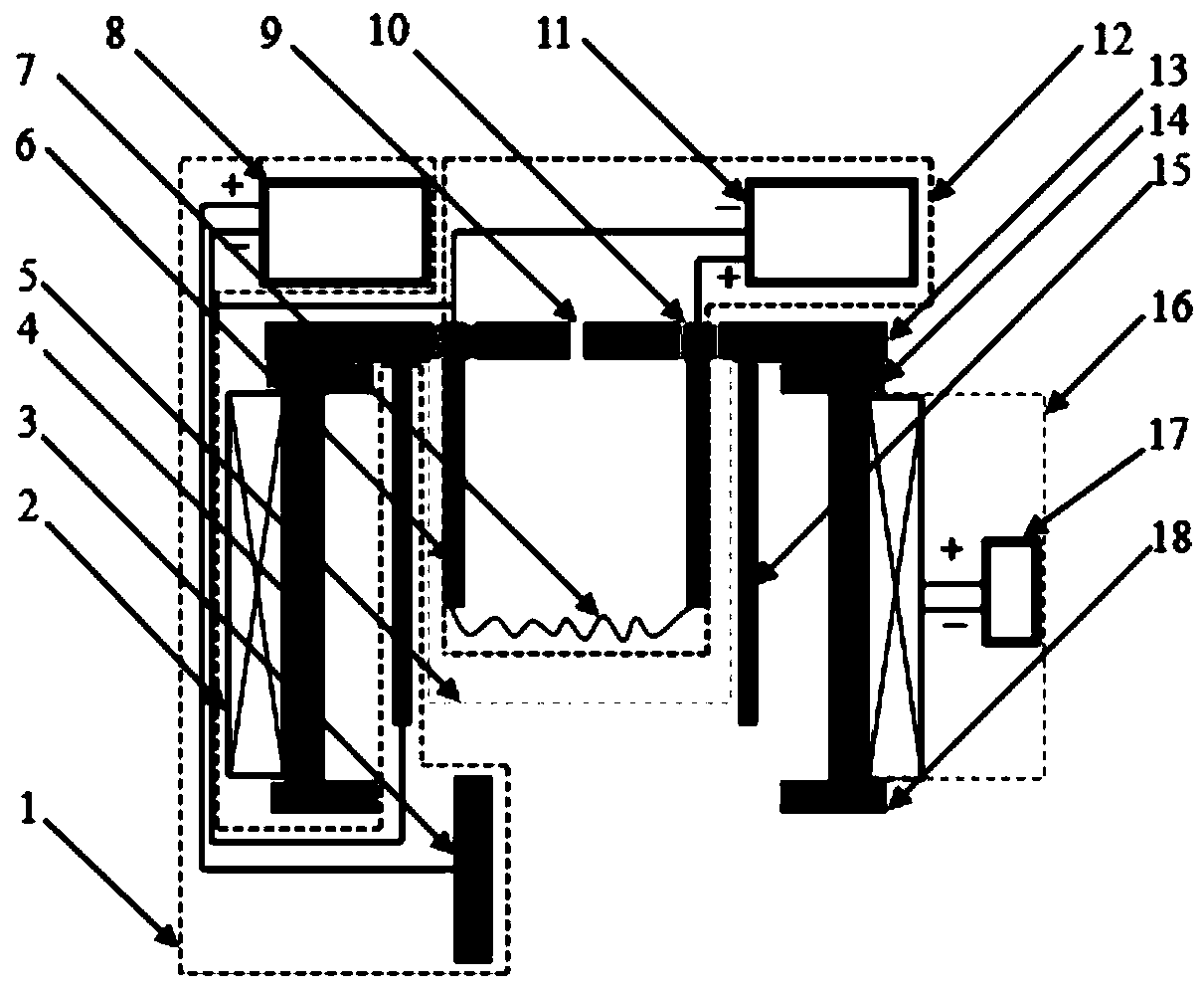
[0070] A gas arc discharge device such as figure 1 As shown, it includes a metal cylinder module 1, a first electromagnetic coil module 16, a hot wire electrode module 12, a vacuum wall and an insulator;

[0071] The metal cylinder module 1 includes an auxiliary anode 3, a metal cylinder 15, and a metal cylinder module power supply 8, the anode of the metal cylinder module power supply 8 is connected to the auxiliary anode 3, and the cathode of the metal cylinder module power supply 8 is connected to the bottom end of the side wall of the metal cylinder 15;

[0072] The first electromagnetic coil module 16 includes a first electromagnetic coil 2 and a first electromagnetic coil control module, and the first electromagnetic coil control module includes a first electromagnetic coil control set and a first electromagnetic coil power supply 17, and the first electromagnetic coil control module The assembly is connected to ...

Embodiment 2

[0088] Embodiment 2: The coupling system between the gas arc discharge device and the vacuum chamber:

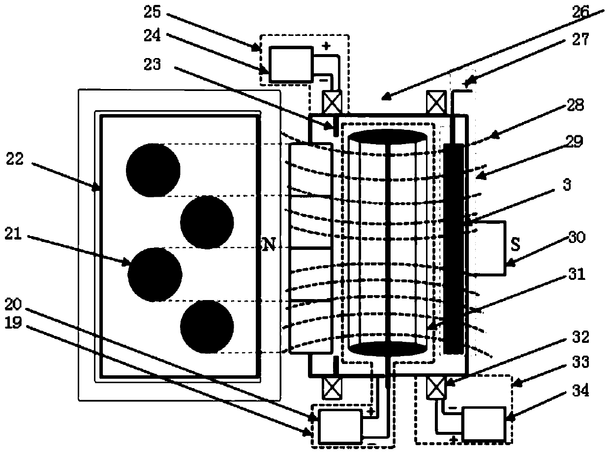
[0089] The present invention also provides a coupling system between the gas arc discharge device and the vacuum cavity, such as figure 2 As shown, the left side is a schematic diagram of the arrangement of the gas arc discharge device 21 in the vacuum chamber 22, and the right side is a detailed cross-sectional view of the structure in the vacuum chamber 22. The vacuum chamber 22 is a closed vacuum container, and the gas The arc discharge device 21 is installed in the vacuum cavity 22, and the workpiece holder module, the second electromagnetic field module 25, the third electromagnetic field module 33, the thermocouple 23, and the air extraction system 30 are also arranged in the vacuum cavity 22;

[0090] exist figure 2 Among them, the auxiliary anode 3 of the gas arc discharge device and the power supply anode 27 of the metal cylinder module are marked with the auxili...

Embodiment 3

[0107] Embodiment 3: the example of the gas arc discharge device of the present invention in generating arc discharge;

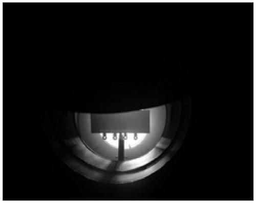
[0108] According to the requirements of this patent, the arc discharge plasma source device is installed and debugged, and the heating wire is selected from tungsten wire. By observing the arc discharge, check the stability of the arc discharge to determine whether the arc starting process is safe and reliable.

[0109] Experimental process: first pump the vacuum chamber to 0.5×10 -4 Below Pa, then argon gas is introduced into the vacuum chamber, and the mass flow controller and slide valve are adjusted to keep the pressure of the vacuum chamber at 0.8Pa. Turn on the hot wire power supply, and other power supplies are in standby mode at this time. When the filament current reaches 120A, slowly turn on the bias power supply, stop adjusting the bias power supply when an arc appears in the plasma source, and observe the discharge in the vacuum chamber. At thi...


PUM


Abstract

The invention provides a gas arc discharge device, a coupling system of a vacuum cavity and an ion nitriding process. A thermal cathode electron emission principle is utilized to coordinate with an auxiliary cathode to generate plasma, and the plasma nitriding is carried out through coupling of a magnetic field module of the device and a cavity axial magnetic field module. The parameters of the gas arc discharge device and the cavity axial magnetic field are controlled to be coupled, the optimal magnetic field parameters are selected, the plasma energy and density in the vacuum cavity are increased, and the optimal nitriding effect is obtained. According to the device and the method, 316L austenitic stainless steel is subjected to 60 min plasma nitriding treatment, the hardness of a nitriding layer can reach 1100 HV0.05, the nitriding depth can reach 50 micron, no nitride is precipitated in the nitriding layer, and the nitriding layer is a single gamma N phase, so that the high hardness and high wear resistance of a nitriding workpiece are ensured.

Description

technical field [0001] The invention belongs to the technical field of metal material surface treatment, and in particular relates to a gas arc discharge device, a coupling system with a vacuum chamber and an ion nitriding process. Background technique [0002] The use of the traditional ion nitriding process will produce N-containing gas or N that is harmful to the environment or personal safety. 2 with H 2 of mixed gas. In the traditional glow ion nitriding technology, some use pure nitrogen as the working gas, but the nitriding efficiency of the traditional glow nitriding process is generally very low, and the thickness of the obtained nitrided layer is relatively thin; and with the nitriding time The increase of the increase will form a layer of nitride precipitation layer on the surface of the workpiece, which will affect the mechanical properties or corrosion resistance of the material itself; in the traditional glow ion nitriding, the workpiece exists as a discharge...

Claims


Application Information

Patent Timeline
IPC IPC(8): C23C8/38
Inventor 刘兴龙蔺增
Owner 泰安东大新材表面技术有限公司
Why Eureka
Try Eureka