
Refrigerating system and process based on biomass energy

A biomass energy and refrigeration system technology, applied in refrigerators, biofuels, refrigeration components, etc., can solve the problems of poor economy, difficult to treat phenol-containing wastewater, low efficiency, etc., to improve reliability, save operating costs and equipment. The effect of high investment and utilization efficiency

Active Publication Date: 2019-06-28
ANHUI JINMEI ZHONGNENG CHEM IND
View PDF6 Cites 0 Cited by
  • Summary
  • Abstract
  • Description
  • Claims
  • Application Information

AI Technical Summary

Problems solved by technology

[0004] The current large-scale utilization of biomass is mainly for power generation and heat supply. The power generation methods include direct combustion power generation and gasification power generation. It is difficult to collect raw materials for direct combustion power generation, the efficiency is low, and its economy is poor
Conventional gasification power generation is mainly through internal combustion engines, which are difficult to achieve large-scale production due to poor stability. Biomass gasification gas turbine power generation has been widely used as an emerging technology. Because gas turbines have high requirements for gas quality, existing production The material gasification gas turbine technology mainly uses pure oxygen as the gasification agent. The gas generated by the gasifier is deeply purified through a complex purification system to obtain high-quality gas. The existing problems are: the operating cost of the air separation system is high, and the gas purification produces The phenol-containing wastewater is difficult to treat, which greatly restricts the promotion of technology

Method used


Image

  • Refrigerating system and process based on biomass energy

Examples


Embodiment 1

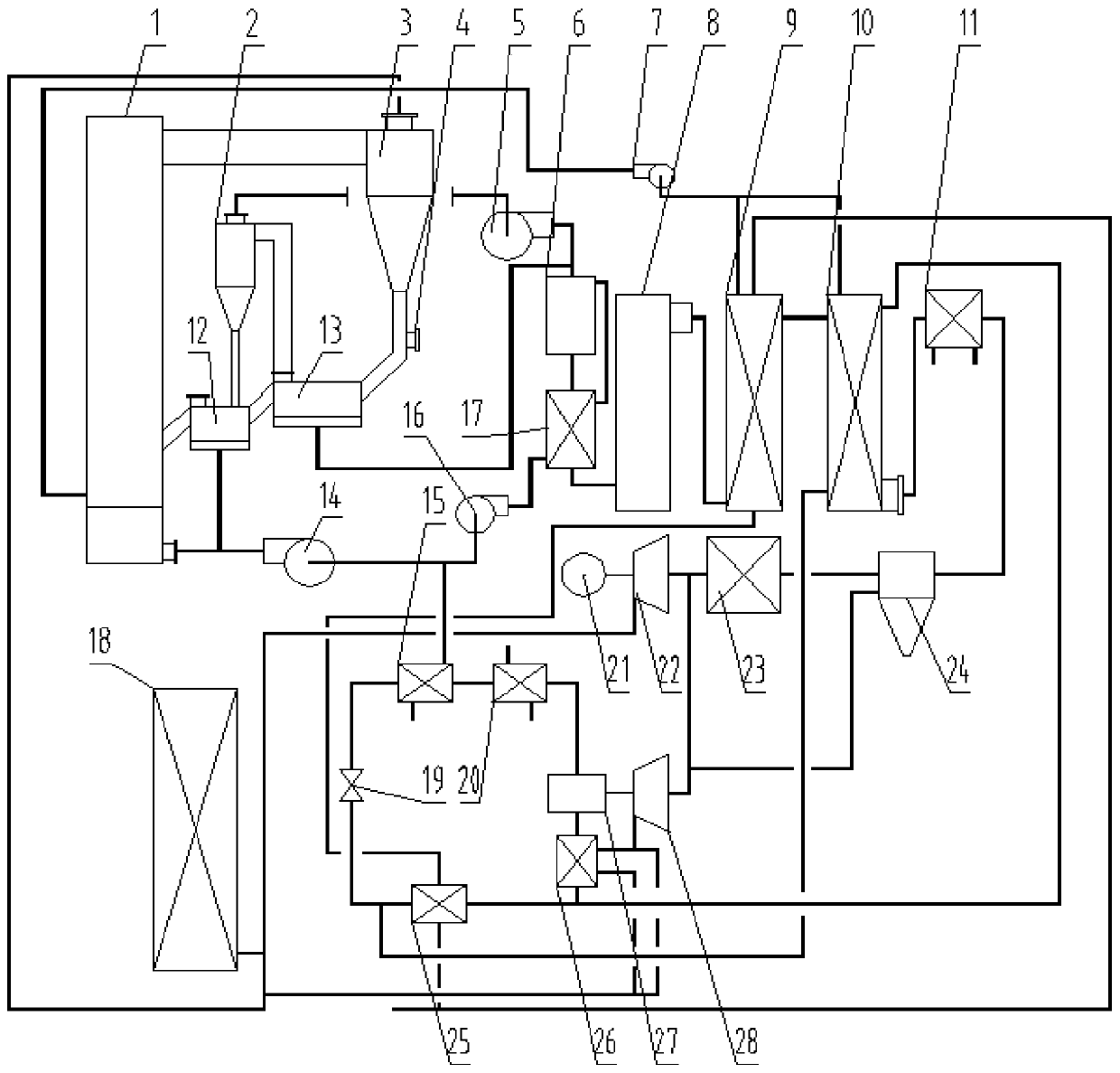
[0062] S1. Rice husk fuel is added from the fuel feeding pipe 4, and the heat carrier, biomass ash and biomass fuel are mixed and fluidized in the pyrolyzer 13. The fluidization medium is high-temperature pyrolysis gas, and the heat carrier is 1mm river sand and oxidation A mixture of calcium powder, the temperature at the inlet end of the pyrolyzer 13 is 780°C, and the temperature at the outlet end of the pyrolyzer 13 is 600°C, and the biomass fuel is pyrolyzed into high-temperature pyrolysis gas and carbon powder, and the carbon powder, heat carrier, and biomass ash are mixed Entering the feeder 12, the high-temperature pyrolysis gas enters the pyrolysis gas separator 2 from the gas outlet on the upper part of the pyrolyzer 13 for gas-solid separation, and the separated carbon powder enters the feeder 12, and undergoes high-temperature pyrolysis after separation. The gas is pressurized and conveyed by the pyrolysis gas booster fan 5;

[0063] S2. The carbon powder, heat carr...

Embodiment 2

[0073] S1. Straw fuel is added from the fuel feeding pipe 4. The heat carrier, biomass ash and biomass fuel are mixed and fluidized in the pyrolyzer 13. The fluidization medium is high-temperature pyrolysis gas, and the heat carrier is 2mm ceramic balls and calcium oxide. The mixture of powders, the temperature at the inlet end of the pyrolyzer 13 is 730°C, and the temperature at the outlet end of the pyrolyzer 13 is 550°C. The biomass fuel is pyrolyzed into high-temperature pyrolysis gas and carbon powder, and the carbon powder, heat carrier, and biomass ash are mixed into the In the feeder 12, the high-temperature pyrolysis gas enters the pyrolysis gas separator 2 from the gas outlet on the upper part of the pyrolyzer 13 for gas-solid separation, and the separated carbon powder enters the feeder 12, and the separated high-temperature pyrolysis gas Through the pyrolysis gas booster fan 5 pressurized delivery;

[0074] S2. The carbon powder, heat carrier, and biomass ash enter...

Embodiment 3

[0084] S1. Sawdust fuel is added from the fuel feeding pipe 4. The heat carrier, biomass ash and biomass fuel are mixed and fluidized in the pyrolyzer 13. The fluidization medium is high-temperature pyrolysis gas, and the heat carrier is river sand and calcium oxide of 2 mm. The mixture of powders, the temperature at the inlet end of the pyrolyzer 13 is 800°C, and the temperature at the outlet end of the pyrolyzer 13 is 690°C. The biomass fuel is pyrolyzed into high-temperature pyrolysis gas and carbon powder, and the carbon powder, heat carrier, and biomass ash are mixed into the In the feeder 12, the high-temperature pyrolysis gas enters the pyrolysis gas separator 2 from the gas outlet on the upper part of the pyrolyzer 13 for gas-solid separation, and the separated carbon powder enters the feeder 12, and the separated high-temperature pyrolysis gas Through the pyrolysis gas booster fan 5 pressurized delivery;

[0085] S2. The carbon powder, heat carrier, and biomass ash en...


PUM


Abstract

The invention discloses a refrigerating system and a process based on biomass energy. The refrigerating system comprises a carrier heating furnace, a high-temperature pyrolyzer, a pyrolyzer, a second-level condenser, a first-level condenser and the like, wherein an outlet of the carrier heating furnace is connected with an inlet of a cyclone dust collector; and an ash discharge pipe on the bottompart of the cyclone dust collector is connected with an inlet of the pyrolyzer. The production process comprises the steps of heating a carrier, pyrolyzing biomass, pyrolyzing tar, utilizing waste heat, purifying fuel gas, producing freeze water, producing hot water, generating power and the like. Through the matching connection of heat energy, the efficiency of the biomass energy can be maximallyutilized, and the advantage of high utilization efficiency is realized; and no tar or waste water is generated in a gasification power generation system, so that the reliability of system operation is improved.

Description

technical field [0001] The invention belongs to the technical field of refrigeration utilization, and in particular relates to a refrigeration system and process based on biomass energy. Background technique [0002] Process production plants often have strict requirements on their internal temperature and humidity. Most of the temperature and humidity in process production plants are controlled by a centralized central air-conditioning system. The central air-conditioning system often requires dehumidification. To the low temperature, the water vapor in the air is condensed into a liquid state, and then the air is heated by hot water to realize the adjustment of temperature and humidity. The operation mode of the existing refrigeration system in the factory area is mainly the coordination of the refrigerator and the gas boiler, that is, the chilled water generated by the refrigerator is used for refrigeration, and the steam or hot water generated by the gas boiler is used f...

Claims


Application Information

Patent Timeline
IPC IPC(8): F25B41/06C10B53/02C10B49/10C10B49/22C10B57/16C10K3/00B01D53/48B01D53/83F02C3/22F02C6/00F02C6/18F25B41/31
CPCY02P20/129Y02E50/10Y02P20/10
Inventor 张林峰宋雨海李兴隆张威风
Owner ANHUI JINMEI ZHONGNENG CHEM IND
Learn More