Supercharge Your Innovation With Domain-Expert AI Agents!

Lightweight fiber laser

A technology of fiber lasers and lasers, which is applied in the field of lasers, can solve problems such as damage to laser components, large volume and weight of lasers, and bulky shell structures, so as to overcome the force of tangential and lateral offsets, improve energy conversion efficiency, The effect of strong environmental adaptability

Pending Publication Date: 2019-07-05
JIANGSU LUMISPOT PHOTOELECTRIC TECH CO LTD
View PDF6 Cites 0 Cited by
  • Summary
  • Abstract
  • Description
  • Claims
  • Application Information

AI Technical Summary

Problems solved by technology

[0004] However, the fiber lasers currently on the market have the following technical defects: (1) Existing fiber lasers generally have relatively strict requirements on the operating environment, which will have a serious impact on the performance of the laser in high temperature and low temperature environments, and the energy conversion efficiency of the laser lower
(2) The existing fiber lasers with a continuous power of 10w or more require additional cooling and heating structures, resulting in a large overall volume and weight of the laser, which makes it difficult to be implanted in some portable devices, and the shell structure is heavy. Complex assembly process
(3) The components and installation structure of the laser have low strength, and the laser cannot withstand high-intensity vibration and strong impact, which may easily cause damage to laser components

Method used


Image

  • Lightweight fiber laser
  • Lightweight fiber laser
  • Lightweight fiber laser

Examples


Embodiment Construction

[0034] In order to make the technical solution of the present invention clearer, the present invention will be further described below in conjunction with the accompanying drawings. Any solution obtained by equivalent replacement and conventional reasoning of the technical features of the technical solution of the present invention falls within the protection scope of the present invention. The fixed connection, fixed arrangement, and fixed structure mentioned in this embodiment are all known technologies known to those skilled in the art, such as welding, hot-melt one-shot molding, screw connection, bolt-nut connection, and riveting.

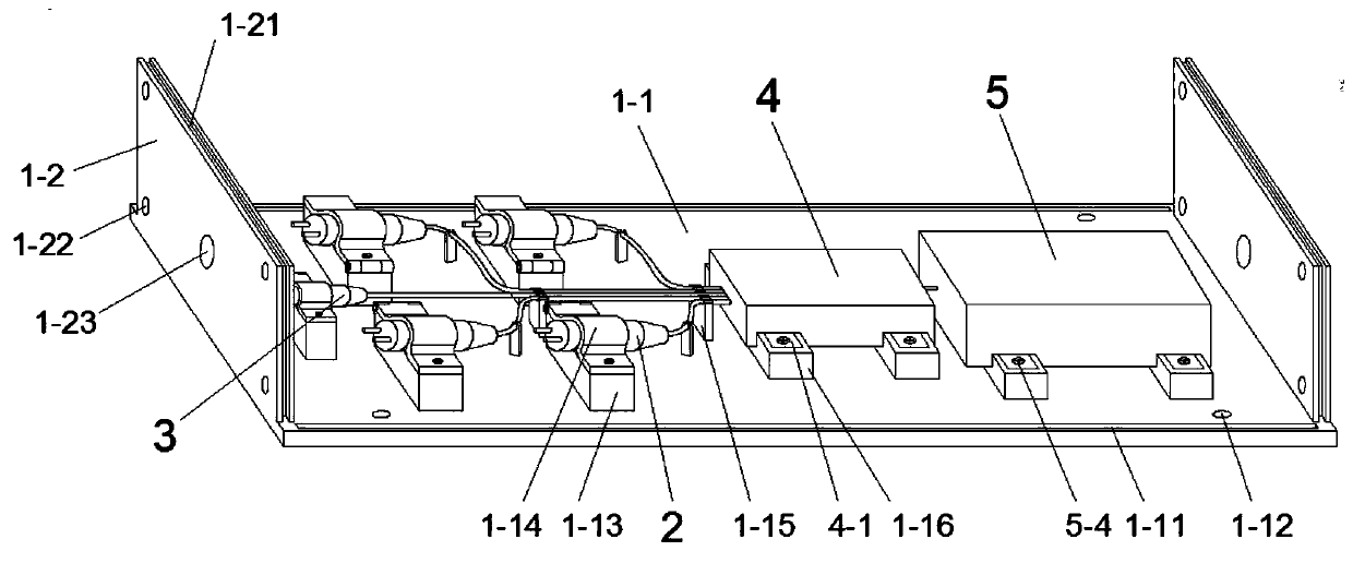
[0035] The semiconductor laser described in the present invention adopts a 10w fiber-coupled semiconductor laser. The emission wavelength of the laser includes two or more of 915nm, 940nm, and 976nm. The output fiber of the semiconductor laser is an optical fiber of 105um / 125um.

[0036] The red laser described in the present invention adopts a co...


PUM


Abstract

A lightweight fiber laser comprising a housing, a semiconductor laser, a red-light laser, a pumping beam combiner, an optical resonant cavity, and silicone rubber, wherein the housing includes a bottom plate, a side plate and a cover plate; the semiconductor laser, a red-light laser, the pumping beam combiner and the optical resonant cavity are all disposed on the upper surface of the bottom plate; the output end of the semiconductor laser is fusion spliced to the input end of the pumping beam combiner through a fiber; the output end of the red-light laser is fusion spliced to the input end ofthe pumping beam combiner through a fiber; the input end of the optical resonant cavity is fusion spliced to the output end of the pumping beam combiner; the optical resonant cavity is provided therein with a high-reflection grating, a doped fiber and a low-reflection grating; and the silicone rubber is disposed in the housing. The housing is high in structural strength. The potted silicone rubber further strengthens the structural stability, assists heat dissipation, and can work normally in severe conditions such as low temperature, high temperature, serious vibration and serious impact. Bymeans of the lightweight and compact structure, the laser can be easily used in small devices.

Description

technical field [0001] The invention relates to the field of lasers, in particular to a lightweight fiber laser. Background technique [0002] A laser is a device that emits laser light. At present, lasers have been widely used in various fields, such as laser welding, laser cutting, laser marking and other technologies in industrial applications. As well as laser radar, laser ranging, laser guidance and many other aspects used in the military field. With the development of lasers, fiber lasers with optical fibers as gain media came into being. [0003] A fiber laser uses a semiconductor laser as the pump source, a doped fiber as the gain medium, and a pair of fiber gratings with different reflectivity to form a resonant cavity. Compared with traditional solid-state lasers, it has many advantages such as small size, high electro-optical efficiency, and easy maintenance, and will be the development direction of lasers in the future. [0004] However, the fiber lasers curr...

Claims


Application Information

Patent Timeline
IPC IPC(8): H01S3/094H01S3/067
CPCH01S3/094042H01S3/06704
Inventor 蔡震陈峰李琮
Owner JIANGSU LUMISPOT PHOTOELECTRIC TECH CO LTD
Features
  • R&D
  • Intellectual Property
  • Life Sciences
  • Materials
  • Tech Scout
  • Unparalleled Data Quality
  • Higher Quality Content
  • 60% Fewer Hallucinations
Learn More